Advertisement
Quick Links
653071
Information
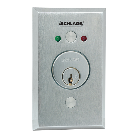
653 Models mount in a standard single-gang box as shown below. Template may be cut out or follow dimensions for prep of mounting area.
See other side for special application notes.
Template
DO NOT PHOTOCOPY THIS DOCUMENT!
TEMPLATE MUST BE TO SCALE.
Blocking Ring required for cylinders over 1-1/8"
Thickness = cylinder length - 1-1/8"
1/16"
Hex set screw
© 2013 Ingersoll Rand
(877) 671-7011
653071 Rev. 02/13-d
650 Series Keyswitches
Installation Instructions & Template
Anti-Pullout Tab (optional)
Recommended Cam:
Schlage P/N: B502-191
B502-948 or equivalent
Anti-Tamper Plugs
(HDP only)
Standard Keyswitch
5A @ 30VAC/VDC
ATS switch closes
when cover is on.
0.025A @ 28VDC
White
LED indicator lights
operate @ 12-24VDC
0.025A @ 28VDC
Recommended cutout for 653 Keyswitches.
6-32 thread
2X
1/4" hole
Drill 4X
2-5/8
2-7/8
3-1/4
NC
Black
C
NO
NO
NO
Red (+)
Black (-)
1-1/2
1-1/4
Remove material to a
depth of 1-3/4" minimum
C L
C L
Red
White
White
Advertisement

Summary of Contents for Schlage 650 Series
- Page 1 650 Series Keyswitches Installation Instructions & Template 653071 Information 653 Models mount in a standard single-gang box as shown below. Template may be cut out or follow dimensions for prep of mounting area. See other side for special application notes.
- Page 2 Functions The 653 Keyswitch comes with all parts (except switch assemblies) to make any function shown below. If switch assemblies are needed, order P/N P653059. NOTE: The Keyswitch uses magnetic springs to activate. Stop Pins Stop Magnet Spring Magnet Dot facing up on Spring Magnet configures momentary action;...