Advertisement
Quick Links
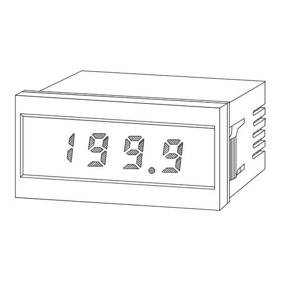
INSTRUCTION MANUAL
DIGITAL PANEL METER
MODEL AP-101 Series
Warning
The mark on the label indicates the measuring
range in the specification of item 1.
Do not disassemble or touch the interior
while the power is ON.
This may cause an electric shock.
Caution
(1)The application of voltage or current exceeding its maximum
allowable value to the input terminals may result in instrument
damage.
(2)The supply of power out of its allowable range may cause fire,
electric shock or instrument failure.
(3)The content of this manual may subject to change without prior
notice for product improvement.
(4)This manual is carefully prepared. However, if any question
arises, or any mistake, omission or suggestion is found in the
content of this manual, contact your nearest our sales agent.
(5)Make this manual available easily anytime.
On the AP-101, connect the control inputs(HOLD,Decimalpoint)to
base-isolated devies when the input signal is 70V DC or more.
1.Specifications
●DC Voltage Measurement
Model &
Measuring
Range Code
Range
AP-101-11
±199.9mV
AP-101-12
±1.999V
AP-101-13
±19.99V
AP-101-14
±199.9V
AP-101-15
±700V
Accuracy: ±(0.1% of rdg +1digit)(at 23℃±5℃ 35 to 85% RH)
[±(0.3% of rdg +1digit)only for AP-101-15]
●DC Current Measurement
Model &
Measuring
Range Code
Range
AP-101-21
±199.9μA
AP-101-22
±1.999mA
AP-101-23
±19.99mA
AP-101-24
±199.9mA
AP-101-25
±1.999A
Accuracy: ±(0.2% of rdg +1digit)(at 23℃±5℃ 35 to 85% RH)
[±(0.3% of rdg +1digit)only for AP-101-25]
Incorrect handling may cause
death or injury.
Attention
Maximum
Maximum
Input
Allowable
Resolution
Impedance
Input voltage
100μV
100MΩ
±250V
1mV
100MΩ
±250V
10mV
10MΩ
±250V
100mV
10MΩ
±500V
1V
10MΩ
±700V
Maximum
Maximum
Internal
Allowable
Resolution
Resistance
Current
100nA
1kΩ
±10mA
1μA
100Ω
±50mA
10μA
10Ω
±150mA
100μA
1Ω
±500mA
1mA
0.1Ω
WATANABE ELECTRIC INDUSTRY CO., LTD.
●Model Configuration
(Example)
AP-101-11-1
Basic Model
2.Common Specifications
Measuring function
Operation method
Input circuit
Input bias current
Sampling speed
Noise elimination
Max. No. of display
digits
Overrange alarm
Display
Polarity
Polarity display
External control
Decimal point
Operating
temperature/humidity
Storage temperature
Power supply
Dimensions
Weight
Dielectric strength
Insulation
resistance
Accessories
Standards
±3A
Setup enviroment
Altitude
1. AC 90V to 132V
2. AC180V to 264V
Power supply
3. DC 5V
4. DC24V
11.±199.9mV
12.±1.999V
Range code
13.±19.99V
14.±199.9V
Series
15.± 700V
The above standards do not apply to the panel meter
with "15 range".
: DC voltage measurement.
Specify one model from among 9
models.
:Dual slope integration
:Single-ended type
:50pA(Typical)
:2.5 times/sec.
:More than 40dB(50/60Hz)(Typical)
:1999
:1999 or -1999 flashes when an input
exceeding the maximum display range
is applied.
:LED(Light Emitting Diode)numeric
element
Height; 14.2mm red
:Automatic Polarity selection
:"-" is displayed automatically if
input signal becomes negative.
:・External display hold
A negative signal of 0V or a contact
signal.
・External start
A positive pulse from 0V to +5V for
more than 400ms. or a contact
signal(open)
:Settable to any digit position
:0 to 50℃/35 to 85%RH
(Nodew-Condense)
: -10 to 70℃,60%RH max.
:For AC, 90V to 132V 50/60Hz
Approx.2.0VA(at 100V)
180V to 264V
For DC, 5V DC ±5% 150mA(MAX)
Isolated
24V DC±20% 40mA(MAX)
Isolated
: 96mm(W)×48mm(H)×73mm(D)
: For AC; Approx.150g(Mainframe)
For DC; Approx.85g(Mainframe)
: For AC; 2100VAC for 1 minute between
power supply terminal and input
terminal/COMMON
For DC; DC±500V between input (LO)
terminal and power terminal(0V)
:More than 100MΩ at 500VDC
between power terminal and input
terminal
:Instruction manual, connector
: EN61326-1:2006
EMI:Class A
EMS:Industrial locations
※Cable length:30m or less
※In the case of DC drive DC power
supply port: DC connections between
parts of equipment
EN61010:2001
The above standards do not apply to
the panel meter with "15 range".
: Installation categoryⅡ,
Pollution degree2
: 2000m max.
(3/4)
21.±199.9μA
22.±1.999mA
23.±19.99mA
24.±199.9mA
25.±1.999A
Advertisement

Related Manuals for WATANABE ELECTRIC INDUSTRY CO., LTD AP-101-11

Summary of Contents for WATANABE ELECTRIC INDUSTRY CO., LTD AP-101-11
- Page 1 0.1Ω ±3A the panel meter with “15 range”. Accuracy: ±(0.2% of rdg +1digit)(at 23℃±5℃ 35 to 85% RH) Setup enviroment : Installation categoryⅡ, [±(0.3% of rdg +1digit)only for AP-101-25] Pollution degree2 Altitude : 2000m max. WATANABE ELECTRIC INDUSTRY CO., LTD.
- Page 2 1 to 3. Use a 2-core shielded cable and connect the shield to the input LO side at one point near the signal source. 6-16-19, Jingumae, Shibuya-ku, Tokyo 150-0001, Japan 6-16-19, Jingumae, Shibuya-ku, Tokyo 150-0001, Japan WATANABE ELECTRIC INDUSTRY CO., LTD. Phone: (81)3-3400-6140 Phone: (81)3-3400-6141 WATANABE ELECTRIC INDUSTRY CO., LTD.
Need help?
Do you have a question about the AP-101-11 and is the answer not in the manual?
Questions and answers