Advertisement
Quick Links
1. SAFETY INFORMATION.
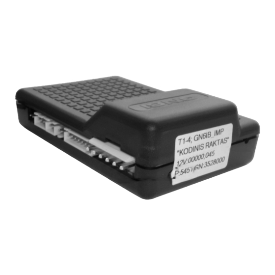
The 'GN6Ib' is a vehicle alarm system designed for use with cars with their original remote controlled central lock. The 'GN6Ib' (Fig. 1)can
be used in most cars (except cabriolets) with petrol or diesel engines, 12V batteries with the negative pole connected to "ground" (i.e. vehicle
body).
The vehicle alarm system must be installed inside the passenger compartment of the vehicle, in a place difficult to access in accordance with
the manufacturer's supplied wiring instructions.
The manufacturer of the alarm system recommends the following:
a) choose a qualified vehicle alarm systems installer to fit the device;
b) mount the system unit in place free from moisture and other elements that could pose to corrode the device. It should also be placed as far
away as possible from any heat emitting elements in the passenger compartment and sources of electromagnetic interference (e.g. vehicle
computer, fans, relay blocks);
c) avoid mounting the system unit directly onto metal parts of vehicle to prevent the accumulation of condensation in the system unit;
d) mount the system unit so that the wire connectors are going from the bottom side of the unit;
e) avoid placing wires next to moving or hot parts of vehicle;
f) don't overload the alarm system circuits, see the following circuit requirements:
cut - off circuit
current ...............................................................................
1
optional control circuit (OC)
siren drive circuit
current............................................................................
1
right direction indicator control circuit
left direction indicator control circuit
g) For EU countries only use settings compatible with EU directives.
2. ALARM SYSTEM INSTALLATION SEQUENCE.
a) select the system adaptation method to the central lock action sequence (see chapter 7);
b) install the system in accordance with the selected adaptation method and corresponding wiring diagram (see chapters 4, 5, 6);
c) progress through the system learning procedure (see chapter 7);
d) customize alarm system if default settings are not suitable (see chapters 3, 7);
e) fill out an installation certificate (see chapter 8).
3 . PIN, FN, SN CODES.
To enter the override and setup mode, to customize the alarm system according to the required security level the PIN, FN and SN codes are
required. The factory preset 4-digit PIN code is written on the alarm's 'system information' sticker (see Fig. 1). It is recommended that the PIN code
is changed after alarm system installed (N.B. remember the new PIN code by keeping a record of it in a file so it may be retained for future
reference).
3.1. THE OVERRIDE MODE.
The alarm system override mode is used in the following scenarios: if the remote control unit is lost; if the remote's battery becomes fully
discharged; if the car is being repaired. With this mode ON, the alarm system does not respond to the sensor as it is temporarily disabled, therefore
the following occurs as a result: the device will not immobilize the engine; the car will not become alarmed; the system's LED flashes frequently.
The override mode can be turned ON in two ways, by the use of the PIN code.
3.1.1. TURNING ON THE OVERRIDE MODE WITH THE HELP OF THE OVERRIDE BUTTON.
The most convenient way to turn the override mode ON is to enter the PIN code with the override button. If the override button is installed,
check your notes with alarm system's PIN, then press the override button as many times as the value of the first digit of the PIN (N.B. the time
between the presses should not exceed 1 second) and wait for a 1 second long LED flash which means that the first digit is entered. In the same
way enter the second, third and fourth digits of the PIN. Upon correct entry of all four digits of the PIN code the LED emits frequent flashes. If
you made a mistake while entering the PIN code, wait for a 1 second long LED flash, wait for 2 seconds and follow 3.1.1 all over again. If the
'anti-carjack' or immobilizer features are activated the system will respond to the first press of the override button as to the control of the
'anti-carjack' or immobilizer function. The system will respond to the next presses made as if the PIN code is being entered.
3.1.2. TURNING ON THE OVERRIDE MODE WITH THE IGNITION KEY.
If the override button is not installed, open the vehicle door and turn the ignition ON. After a short pause the system LED starts flashing
double flashes. Count these flashes until the number of double flashes (1 double flash = 1) corresponds with the first digit of the PIN code. Turn the
ignition OFF for a short time and turn it ON again. Count the double flashes until the number corresponds with the second digit of the PIN code.
Turn the ignition OFF and ON again. Enter the remaining two digits of the PIN code in the same way. Upon correct entry of all four digits of the
PIN code the LED emits frequent flashes. If you made a mistake while entering the PIN code, turn OFF the ignition, close the doors, and follow
3.1.2 all over again.
3.1.3. TURNING OFF (EXIT) THE OVERRIDE MODE.
Enter the PIN code and within 8 minutes of doing so enter the code '11' in a same way as PIN.
3.2. ALARM SYSTEM SETUP MODE.
The 'GN6Ib' features up to 85 system settings. Due to these settings the 'GN6Ib' can be adjusted to a particular vehicle or relevant customer's
requirements. The alarm system is supplied with the factory preset default settings listed in Table 2, chapter 8. If the default settings are not
suitable for the user you can customize them. To customize the alarm system please do the following steps:
a) turn override mode ON by entering the PIN appropriately;
b) within 8 minutes select the function (FN) which operation you want to change and enter the 2-digit FN code;
c) to change the function operation according to the new setting enter the 1-digit setting number (SN);
d) now exit setup mode by entering the code '11'.
For more details see chapter 7.
VEHICLE ALARM SYSTEM 'GN6Ib'
Models 'GN6Ib.U', 'GN6Ib.P', 'GN6Ib.UPS'. Installlation manual.
current .................................................
1 1
current ........................................
5
current ..........................................
2
PIN code
Fig. 1. 'GN6Ib' external view.
25 A;
0.13 A;
2 A;
7 A;
7 A;
Sticker
Advertisement

Related Manuals for Kodinis Raktas GN6Ib.U

Summary of Contents for Kodinis Raktas GN6Ib.U
- Page 1 VEHICLE ALARM SYSTEM 'GN6Ib' Models 'GN6Ib.U', 'GN6Ib.P', 'GN6Ib.UPS'. Installlation manual. 1. SAFETY INFORMATION. The 'GN6Ib' is a vehicle alarm system designed for use with cars with their original remote controlled central lock. The 'GN6Ib' (Fig. 1)can be used in most cars (except cabriolets) with petrol or diesel engines, 12V batteries with the negative pole connected to "ground" (i.e. vehicle body).
- Page 2 4. 'GN6Ib' WIRING DIAGRAM USING COMPUTER LEARNING OR AUTOMATIC LEARNING. 14V DC 25A max. Cut off circuit Ultrasonic sensor (GN6Ib.SPU) Ultrasonic sensor Contacts of Relay K1 (GN6Ib.SPU) Switch in the door strut, 1 2 3 luggage compartment, and / or bonnet switch Right direction indicators...
- Page 3 5. 'GN6Ib' WIRING DIAGRAM USING MANUAL LEARNING IN CASE OF LOW LOGIC LEVEL COMMUTATION. 14V DC 25A max. Cut off circuit Ultrasonic sensor (GN6Ib.SPU) Ultrasonic sensor Contacts of Contacts of Relay K1 Relay K1 (GN6Ib.SPU) 1 2 3 Switches in the door strut, luggage compartment and / or bonnet switch Right direction...
-
Page 4: Manual Setup
7. THE ALARM SYSTEM SETUP. Default factory settings and available settings are listed in Table 2 of chapter 7.4. If default settings are not suitable there are 2 ways to change them. 7.1. MANUAL SETUP: a) turn the override mode ON by entering the PIN; b) the system LED will start frequently flashing;... -
Page 5: Available Settings
1 – 22 'Anti-carjack' delay time adjustment range is from 5 to 110 seconds. FN=25 Function: OPERATION OF THE OVERRIDE BUTTON (FOR GN6Ib.U ', ' GN6Ib.P ONLY) ’ The override button press is available at once as the 'anti-carjack' process is triggered. - Page 6 0 to 8 seconds. FN=36 Function: ADJUSTMENT OF BUILT-IN ULTRASONIC SENSOR (FOR GN6Ib.U, GN6Ib.UPS ONLY). The built-in ultrasonic sensor sensitivity is adjusted by SN value entry. Default factory setting – SN=8. Sensitivity adjustment range is from 1 to 16 (from 1 to 20 –...
- Page 7 The FN71 shows the latest trigger and the FN72, FN73 shows previous FN=73 triggers accordingly). FN=75 Function: ALARM SYSTEM OPERATION WHEN BUIT-IN ULTRASONIC SENSOR IS TRIGGERED (FOR GN6Ib.U ’, ' GN6Ib.UPS ONLY) The direction indicators are flashing and siren sounds if the sensor is triggered. SN=1 The direction indicators are flashing only if the sensor is triggered.
-
Page 8: Certificate Of Installation
8. CERTIFICATE OF INSTALLATION. I, undersigned qualified installer certify that installation of (Name, Surname) the below described vehicle alarm system has been carried out by myself pursuant to installation manual supplied by the manufacturer of the system. Vehicle description: Manufacturer and model: Serial number: Registration number: Description of vehicle alarm system:...