Advertisement
Quick Links
Electrical Connection, SP1-xx
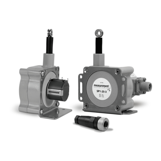
SP1 Installation Guide
com (1)
includes:
SP1-4
SP1-4-3
SP1-12
SP1-12-3
SP1-25
SP1-25-3
+out (2)
SP1-50
SP1-50-3
regulated
DC supply
(30V max)
celesco.com
Electrical Connection, SP1-xx-3
+in (3)
4
mating plug
+in
(contact view)
pin 1 - brown
+out
+
+
regulated
common
DC supply
(30V max)
–
–
common
Output Signal / Circuit
+in
1 - +in
1
10K
2 - common
2
3 - +out
4 - n/c
3
+out
com
0%
Mating Plug
(SP1-xx-3 only)
optional cordset
#9036810-0040
customer supplied electrical cable,
pin 3 - blue
(.25 in [6 mm] max. dia.)
+out
1
4
2
pin 2 - white
3
contact view
2.4" [60mm]
common
Cable Exit/Connector Direction
V
(+out)
100%
SP1-xx-3 shown
To change cable exit direction, simply
remove the 3 mounting bracket screws
and rotate sensor body to 1 of 4 options.
To change connector direction (SP1-xx-3 only),
remove the 4 cover screws and carefully rotate
to desired direction.
alternate installation
alternate cable exits*
.53
[13,4]
1.67
[42,5]
1.38
1.38
1.40
[35,1]
[35,1]
[35,5]
.54 [13,8]
alternate connector
positions*
*note: SP1-xx-3 shown
Advertisement

Related Manuals for celesco SP1

Summary of Contents for celesco SP1
- Page 1 1 of 4 options. (.25 in [6 mm] max. dia.) alternate connector +out +out To change connector direction (SP1-xx-3 only), positions* regulated regulated pin 2 - white remove the 4 cover screws and carefully rotate...
- Page 2 [50,8] Complete Specs: celesco.com/_datasheets/sp1.pdf [37,2] (2 plc.) 1.10 [27,9] 1.19 2.23 [56,6] 1.90 [48,3] [30,1] [20,3] [18,3] [15,2] 2.34 [59,5] 2.52 [64,0] 1.85 [46,9] in [mm] in [mm] in [mm] 2.23 [56,6] in [mm] version: 1.0 / item no: SP1-MANUAL...