Advertisement
Quick Links
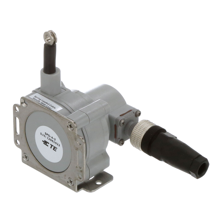
SPD Installation Guide
Includes: SPD-4-3, SPD-12-3, SPD-25-3
& SPD-50-3
4
celesco.com
Electrical Connection
4–20 mA Output
optional cordset
#9036810-0040
brown - pin 1
4–20 mA
+
8–40
black - pin 4
Vdc
return
–
Pin#
Description
1
1 - V+ (8-40 Vdc)
2 - n/c
2
3 - n/c
3
4 - Output Signal (4-20mA)
mating plug
(contact view)
Electrical Connection
0–10 Vdc Output
optional cordset
#9036810-0040
brown - pin 1
0–10 Vdc
+
12–32
black - pin 4
white - pin 2
Vdc
common
–
Pin#
Description
1
1 - V+ (12-32 Vdc)
2 - Output Signal (0-10Vdc)
4
2
3 - n/c
3
4 - Common
mating plug
(contact view)
Electrical Connector
included M12 mating plug
customer supplied electrical cable,
(.25 in [6 mm] max. dia.)
1
4
2
3
contact view
2.4" [60mm]
Output Signal
0%
100%
Output
0% fs.
100% fs.
4...20 mA
4 – 4.25 mA 19.2 – 20 mA
0...10 Vdc
0 – .2 Vdc
9.5 – 10 Vdc
Cable Exit/ Connector Direction
alternate installation
To change cable exit direction, simply
remove the 3 mounting bracket screws
and rotate sensor body to 1 of 4 options.
To change connector direction, remove the
4 cover screws and carefully rotate to desired
direction.
version: 1.0 / item no: SPD-MANUAL
Advertisement

Related Manuals for celesco SPD-4-3

Summary of Contents for celesco SPD-4-3
- Page 1 Cable Exit/ Connector Direction 4–20 mA Output 0–10 Vdc Output included M12 mating plug alternate installation SPD Installation Guide customer supplied electrical cable, Includes: SPD-4-3, SPD-12-3, SPD-25-3 (.25 in [6 mm] max. dia.) & SPD-50-3 optional cordset optional cordset #9036810-0040 #9036810-0040 contact view 2.4”...
- Page 2 Top View (w/o bracket) Front View (w/o bracket) Front View (with bracket) Side View (w/o bracket) Side View (with bracket) 1.48 [37,7] .57 [14,6] Ø .15 [3,9] .54 [13,8] Ø .191 [4,19] Ø .191 [4,19] Ø .375 [9,52] Ø .375 [9,52] .165 .165 .53 [13,3]...