Advertisement
Quick Links
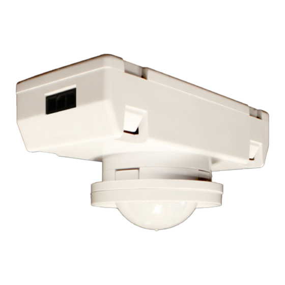
INSTALLATION
• If not pre-installed, locate sensor body so that detector faces down through 1.125" hole in luminaire.
• Align lens assembly legs with holes in sensor body and snap together (max material thickness 0.25").
• Apply foam spacer pads onto sensor body if needed to ensure snug fit with fixture.
• Assembly rotates 15° to enable coverage pattern adjustment after installation.
• To unsnap lens assembly, pry up under lip at spots on lens assembly denoted by arrows.
DIAGRAM 1. INSTALLATION EXAMPLE
COVERAGE PATTERNS
• Recommended for walking motion detection from mounting heights between 8 ft (2.44 m) and 20 ft (6.10 m)
• Initial detection of walking motion along sensor axes at distances of 2x the mounting height up to 15 ft (4.57 m)
9.2
and 1.75x up to 20 ft (6.10 m).
30
• Provides 12 ft (3.66 m) radial detection of small motion when mounted at 9 ft (2.74 m)
• At the 7.5 ft (2.29 m) hanging height of a typical pendant or suspended mount fixture the sensor provides 10 ft
(3.05 m) radial detection of small motion.
• Initial detection will occur earlier when walking across sensor's field of view than when walking directly at sensor
Lens rotates 15° to
7.4
5.4
3.6
1.8
0 m
1.8
3.6
enable adjustment
5.4
24
18
12
6
0 ft
6
12
18
WIRING (DO NOT WIRE HOT)
RED
- 12-24 VDC Power Input
VIOLET - Low Voltage Dim Output (0-10 VDC)
BLACK - Low Voltage Common
Note: Do not connect the dimming wires of
multiple sensors in parallel.
4.6
3.6 2.7 1.8 0.9 0 m 0.9 1.8 2.7 3.6
15
12
9
6
3
0 ft
3
6
9
5-year limited warranty. Full warranty terms located at:
www.acuitybrands.com/CustomerResources/Terms_and_conditions.aspx
Note: Specifications subject to change without notice.
Actual performance may differ as a result of end-user environment and application.
1/2016
DIAGRAM 2. ASSEMBLY DETAIL
PRY UP UNDER LIP ON SIDES WITH
ARROWS TO UNSNAP LENS ASSEMBLY
OPTIONAL SPACER
PAD LOCATION
9.2
30
7.4
24
5.4
18
3.6
12
1.8
6
0 m
0 ft
1.8
6
3.6
12
5.4
18
7.4
24
9.2
30
9 FT MOUNTING
5.5
18
4.6
15
3.7
12
2.7
9
1.8
6
0.9
3
0 m
0 ft
0.9
3
1.8
6
2.7
9
5.4
7.4
9.2
3.7
12
18
24
30
4.6
15
5.5
18
4.6
5.4
12
15
18
OPTIONAL SPACER
PAD LOCATION
15 FT MOUNTING
9.2
30
7.4
24
5.4
18
3.6
12
1.8
6
0 m
0 ft
1.8
6
3.6
12
5.4
18
7.4
24
9.2
30
0 - 10 VDC
5.5
18
LED DRIVER / BALLAST
4.6
15
3.7
12
DC Power (12-24V)
2.7
9
1.8
6
0.9
3
0 m
0 ft
0.9
3
1.8
6
2.7
9
3.7
12
4.6
15
5.5
18
INSTRUCTION
SHEET
MSD (PDT) 7
Embedded 360°
Motion Sensor
SPECIFICATIONS
PHYSICAL SPECS
SIZE: 1.34" H x 1.18" W x 2.62" D
WEIGHT: 3 oz
MOUNTING: Required Hole Size 1.125"
Material Thickness 0.25" max
COLOR: White
ELECTRICAL SPECS
OPERATING VOLTAGE : 12-24 VDC
CURRENT DRAW: 4 mA
DIMMING LOAD: Sinks < 20mA;
~40 Ballasts / LED drivers (0-10VDC)
ENVIRONMENTAL SPECS
OPERATING TEMP: 32° to 140° F (0° to 60° C)
RELATIVE HUMIDITY: 20 to 90% non-condensing
ROHS COMPLIANT
© 2016 Acuity Brands Lighting Inc., All Rights Reserved.
Advertisement

Summary of Contents for Acuity Controls MSD 7
-
Page 1: Specifications
INSTALLATION • If not pre-installed, locate sensor body so that detector faces down through 1.125” hole in luminaire. • Align lens assembly legs with holes in sensor body and snap together (max material thickness 0.25”). • Apply foam spacer pads onto sensor body if needed to ensure snug fit with fixture. •... - Page 2 MSD (PDT) 7 INSTRUCTION SHEET PAGE 2 PROGRAMMING INSTRUCTIONS DETAILED FUNCTION TABLES (CONT.) PLEASE READ ALL 3 STEPS BEFORE PROGRAMMING 7 Sunlight Discount Factor 1. Enter a programming function by pressing button the number of times as the desired function number Value used to improve the tracking accuracy of a photocell during periods of high daylight.