Advertisement
Quick Links
REPLACEMENT PARTS OF FILTER
Key No.
Part No.
1
88281550B
6 Way 1.5" Valve with 1.5" union set x 3 and pressure gauge (Black)
1
88281551B
6 Way 2" Valve with 2" union set x 3 and pressure gauge (Black)
2
06021013
Plastic Pressure Gauge with O-Ring
2
01111048
Connector for Pressure Gauge/Stopper
3
89280102B
1.5" union set (Black) with O-ring
3
89280102W
1.5" union set (White) with O-ring
3
89280103B
2" union set (Black) with O-ring
3
89280103W
2" union set (White) with O-ring
4
03021035
M6 Nut
5
89012512
Clamp Kit
6
01111101
Star-Shaped Nut
7
03011166
M6×110mm Screws
8
02010007
O-Ring
9
89012501
Filter Tank for MFV17
9
89012502
Filter Tank for MFV20
9
89012503
Filter Tank for MFV24
9
89012504
Filter Tank for MFV27/MFV27A
9
89012505
Filter Tank for MFV31/ MFV31A
9
89012506
Filter Tank for MFV35
10
89012507
Lateral Assembly with Center Pipe for MFV17
10
89012508
Lateral Assembly with Center Pipe for MFV20
10
89012509
Lateral Assembly with Center Pipe for MFV24
10
89012510
Lateral Assembly with Center Pipe for MFV27A
10
89012513
Lateral Assembly with Center Pipe for MFV27
10
89012511
Lateral Assembly with Center Pipe for MFV31A
10
89012514
Lateral Assembly with Center Pipe for MFV31
10
89012515
Lateral Assembly with Center Pipe for MFV35
11*
01172007
Laterals (115mm)
11*
01172008
Laterals (126mm)
11*
01172010
Laterals (185mm)
12
89011601
Water Drain Set
13
01111059
16-21inch Filter Base
13
01111062
21-28inch Filter Base
13
01112037
31-35inch Filter Base
Notes:
11* MFV17 should have 8pcs of Lateral (115mm)
11* MFV20/ MFV24/ MFV27A should have 8pcs of
Lateral (126mm)
11* MFV27/ MFV31/ MFV35 should have 4pcs of lateral
(115mm) and 4pcs of lateral (185mm)
Description
4-4
Qty
1
1
1
1
3
3
3
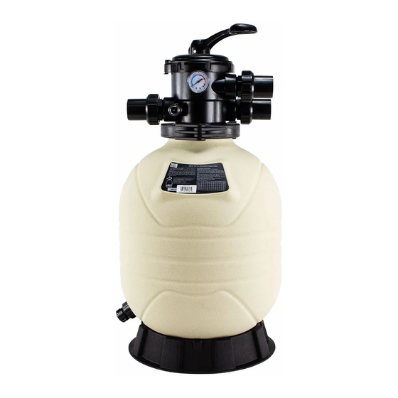
FILTER
MAX ERIES
S
3
1
MODEL: MFV17 / MFV20 / MFV24 / MFV27A / MFV27 / MFV31A / MFV31 / MFV35
1
1
1
Your Emaux "Filter Max" Filter is a high performance
c o r r o s i o n - p r o o f f i l t e r t h a t h a s s u p e r i o r f l o w
1
characteristics that is with the ease of operation.
1
E v e r y t h i n g i s m a d e s i m p l e f r o m i n s t a l l a t i o n ,
1
operation to the maintenance of the filter. Your
1
"Filter Max" filter will be your pool filtration partner
t h a t p r o v i d e s c l e a r w a t e r w i t h t h e l e a s t
1
maintenance hassle and care.
1
BEFORE INSTALLATION BE SURE
1
WARNING
TO READ ALL INSTRUCTIONS AND
1
WA R N I N G S C A R E F U L LY. K E E P
1
THIS USER MANUAL FOR FUTURE REFERENCE.
1
1
HOW IT WORKS
1
The Filter uses special sand to remove dirt particles
1
from pool water. Filter sand is loaded into the filter
1
tank to act as the filtration media. The pool water
which contains dirt particles is pumped through your
1
piping system to the filter via the filter control valve.
*
As pool water passes through the filter, dirt particles
*
will be caught by the sand bed and filtered out. The
*
cleaned pool water is returned from the bottom of
the Filter Tank, through the control valve and back to
1
the pool through your piping system. The entire
1
process is continuous and automatic. It is this process
1
that provides the filtration and circulation of water in
your pool.
1
With the filtration process, dirt will accumulate and
becomes saturated in the filter tank. Pressure in the
tank will increase and the resistance of water flow
will occur. This means it is time to clean (backwash)
your filter. Another indication to know when to clean
(backwash) the filter is by checking the pressure
gauge reading. Backwash operation should be
performed when the pressure increases by 10psi
above the pressure when it was clean. Typically a
clean filter will run at 10 to 15psi, so take note of the
pressure gauge reading when the filter was installed.
When the pressure reaches approximately 20 to
25psi or 50% increase from the clean reading,
proceed to the Backwash operation.
WARNING: turn off the pump before switching the
control valve handle.
To perform the Backwash operation, position the
handle on the control valve to "Backwash", the
water flow is automatically reversed through the
filter so the water is directed from the bottom of the
tank, up through the sand, flushing the trapped dirt
and debris out of the waste line. The duration of the
backwash operation will depends on how dirty your
filter is. Check the sight glass to see when the water
b e c o m e s c l e a r . I t i s r e c o m m e n d e d t h a t t h e
backwash should be at least 2 minutes long.
O n c e t h e b a c k w a s h o p e r a t i o n h a d b e e n
completed, the filter should go through the process
of "Rinse" and then back to "Filter". To perform the
different operations, position the handle on the
control valve as indicated.
INSTALLATION
Installation had been made simple, the only tools
needed is a screwdriver and pipe sealant for plastic.
The filter should be installed as close to the pool as
possible, but keep a distance of at least 5 feet
(1.5m). Locate the Filter on rigid, level surface,
preferably in a dry, shaded, and well-ventilated
area. Prior to installation give consideration to the
following: Position of suction, return, and waste
connections. Access for backwashing operation
and servicing; protection from sun, rain, splashing,
etc; Drainage of filter room; Ventilation and
protection of the motor.
1)Place the empty tank in position.
2)Fill the tank with water to the level that covers the
laterals (crepinas), or about 1/3 of the tank height
is recommended. This will avoid damages to the
laterals (crepinas) by the force of the sand when
pouring into the filter.
Model MFV17, the Multiport Control Valve had been
pre-assembled. Remove the Multiport Control Valve
from the tank by unfastening the screw from the
Clamp. Place the Sand Fill Cover over the tank
opening to prevent the sand from getting into the
standpipe.
Model MFV20, MFV24,
MFV2
7A
, MFV2 , MFV31A,
7
MFV31, MFV35, the Sand Fill Cover had been pre-
assembled.
MFV17 MFV20 MFV24
MFV27A MFV31A MFV27
MFV31 MFV35
1)Sand fill cover.
Add water to cover
laterals and add sand.
3)Add water
2)Place
to cover
on tank
laterals and
opening
add sand.
1-4
EMFI16021902
Advertisement

Related Manuals for emaux MFV17

Summary of Contents for emaux MFV17
- Page 1 2" union set (Black) with O-ring FILTER MAX ERIES 89280103W 2" union set (White) with O-ring 03021035 M6 Nut MODEL: MFV17 / MFV20 / MFV24 / MFV27A / MFV27 / MFV31A / MFV31 / MFV35 89012512 Clamp Kit 01111101 Star-Shaped Nut 03011166 M6×110mm Screws Your Emaux “Filter Max”...
- Page 2 (From pump) pipe SPECIFICATIONS to the waste. You can also use this position to vacuum heavy concentration of debris. Outlet MODEL NO. MFV17 MFV20 MFV24 MFV27A MFV27 MFV31A MFV31 MFV35 (To pool)