Advertisement
Quick Links
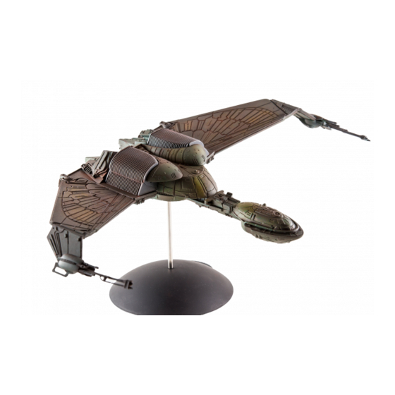
highly detailed plastic assembly model kit
KLINGON BIRD OF PREY
ASSEMBLY INSTRUCTIONS
SUB-ASSEMBLIES:
GENERAL ASSEMBLY:
This highly detailed
intended to be built in sub-assemblies. This
kit features precision-tooled parts for ease of
makes building the kit far more manageable. It
assembly, but care and patience must be exercised
is very important to note that you will also find
to achieve optimal results. It is recommended that
it extremely advantageous to apply paint and
the builder examine the instructions carefully and
decals to sub-assemblies before
do a dry test fit of parts before applying
completing final assembly. Please see the
cement. You will find this very helpful, as it will
other side of this instruction sheet for details on
allow you to gain a clear understanding of how
complex paint and decal placement.
the parts fit together in order to best plan painting
and final assembly.
round2models.com
KEY TO NUMBERING SYSTEM
Special thanks to Edward Holt for developing the landing
1
Opaque plastic part (1-59)
Step number (1-6)
1
parts included in this kit.
Clear plastic part (400-401)
400
Buildup pictured by E James Small. For excellence in model
building, visit his web site at smallartworks.ca
1
RADIATOR ASSEMBL Y
CRUISE MODE
28
26
27
25
30
29
ATTACK MODE
34
32
33
31
36
Cement starboard radiator baffle pieces
35
(32, 34 & 36) together as shown. Cement
port radiator baffle pieces (31, 33 & 35)
radiator baffles as shown for the "wings
LANDING MODE
45
44
48
49
46
®
& © 2010 CBS Studios Inc. © 2010 Paramount Pictures Corp. STAR TREK and related marks are
trademarks of CBS Studios Inc. All rights reserved. AMT is a registered trademark of Learning
Curve Brands, Inc. used under license to Round 2, LLC. ©2010 Learning Curve Brands, Inc. All
rights reserved. Round 2 and design are trademarks of Round 2, LLC. © 2010 Round 2, LLC,
South Bend, IN 46628 USA. Product and designed in the USA. Made in China. All rights reserved.
2
WEAPONS ASSEMBL Y
AMT664
Cement starboard
wing pylon and
phaser cannons outer
and inner pieces (18
& 16) together
Cement port wing
pylon and phaser
cannons outer and
inner pieces (17 &
15) together.
®
3
LANDING GEAR ASSEMBL Y
A.
If building the ship in
Note that this kit is
either flight mode,
cement closed landing
bay doors (42) and
move ahead to step 4.
If building in the landed
mode, cement landing
gear well (43) into
upper hull (2) as shown
and execute the
following steps.
B.
54
Cement starboard radiator baffle
pieces (26, 28 & 30) together as shown.
Cement port radiator baffle pieces (25,
27 & 29) together as shown. Assemble
both radiator baffles as shown for the
56
"wings up" cruise mode.
NOTE: The builder has the option to
build the ship in one of three modes.
Be sure to study upcoming steps to
ensure the right option is executed.
C.
Cement upper legs and lower
legs together as shown.
together as shown. Assemble both
down" attack mode.
Cement starboard radiator baffle
pieces (45, 47 & 48) together as
shown. Cement port radiator
baffle pieces (44, 46 & 49)
together as shown. Assemble both
radiator baffles as shown for the
"landing" mode.
ASSEMBLED
LEG
18
16
15
2
42
53
Cement secondary port
landing bay door (54) to
primary port landing bay
secondary starboard landing
bay door (55) to primary
starboard landing bay door
(52). Cement assembled port
58
58
landing bay door to assembled
landing gear well on port side.
59
Repeat for starboard. Cement ramp
55
railings (59) to landing ramp (56).
52
Cement landing ramp (56) to
assembled landing gear well as
59
shown. Cement ramp support rods (58)
to landing ramp (56) and assembled
landing gear well as shown.
D.
For additonal landing gear assembly
tips, visit our website at
round2models.com/workbench
UPPER
LEG
LOWER
LEG
Cement landing gear assembly C into landing gear assembly B as
shown. Cement landing gear support (57) onto landing gear assembly
B and landing gear assembly C as shown. Cement foot pads (50 & 51)
to landing gear assemblies C.
4
WING ASSEMBL Y
17
PORT
Cement upper port wing (11) and lower port
wing (13) together. Cement inner cooler (41 &
23) together. Cement assembled inner cooler
to assembled port wing as shown. Cement
port wing pylon and phaser cannon assembly
to assembled port wing. Cement the chosen
port radiator baffle
assembly to
assembled port wing.
WING PYLON &
PHASER
ASSEMBLY
6
(PORT)
STARBOARD
Cement upper starboard wing (14) and
lower starboard wing (12) together.
Cement inner cooler (40 & 24)
43
together. Cement assembled inner
cooler to assembled starboard wing as
shown. Cement starboard wing pylon
and phaser cannon assembly to
assembled starboard wing. Cement the
chosen starboard radiator baffle
assembly to assembled starboard
wing.
RADIATOR BAFFLE
5
HULL ASSEMBL Y
A.
10
door (53). Cement
B.
LANDING GEAR
ASSEMBLY
7
C.
5
22
21
HULL
ASSEMBLY B
41
23
RADIATOR BAFFLE
ASSEMBLY
(PORT)
11
13
WING PYLON &
PHASER
ASSEMBLY
24
(STARBOARD)
40
14
ASSEMBLY
(STARBOARD)
12
1
9
4
Cement port hull panel (9) to upper hull
(1) as shown. Cement starboard hull
panel (10) to upper hull (1). Cement port
3
hull side panel and starboard hull side
panel (3 & 4) to upper hull (1) as shown.
37
HULL
ASSEMBLY A
37
Cement photon torpedo emitter
(401) inside photon emitter housing
(7) as a shown. Cement assembled
photon torpedo emitter inside
8
forward bulkhead (6). Cement
torpedo conduit (8) to lower hull
(2). Cement lower hull (2) to hull
assembly A. Cement assembled
bulkhead to assembled hull. Cement
bussard scoops (37) to both sides of
6
hull assembly A.
401
Cement cloaking generator (5) to
20
hull assembly B. Cement
starboard shield panel (22) to
starboard radiator shield (20).
Cement port shield panel (21) to
port radiator shield (19). Cement
assembled port and starboard
radiator shields to hull assembly
19
B. Cement warp drive housing
(400) to hull assembly B. as
shown.
400
A664-201
Advertisement

Related Manuals for AMT STAR TREK KLINGON BIRD OF PREY


Summary of Contents for AMT STAR TREK KLINGON BIRD OF PREY
- Page 1 B and landing gear assembly C as shown. Cement foot pads (50 & 51) trademarks of CBS Studios Inc. All rights reserved. AMT is a registered trademark of Learning Curve Brands, Inc. used under license to Round 2, LLC. ©2010 Learning Curve Brands, Inc. All to landing gear assemblies C.
- Page 2 FINAL ASSEMBL Y PAINTING TIP: PAINT ENTIRE DECAL APPLICATION: SHIP WITH THE EXCEPTION OF Cement starboard wing assembly 1. Dip the decal in water for 10 seconds. For best THE RADIATOR BAFFLES PALE GREEN. ONCE ALL DETAILS ARE and port wing assembly to hull results, mix one drop of common dish washing PAINTED.