Advertisement
Quick Links
SERVICE MANUAL
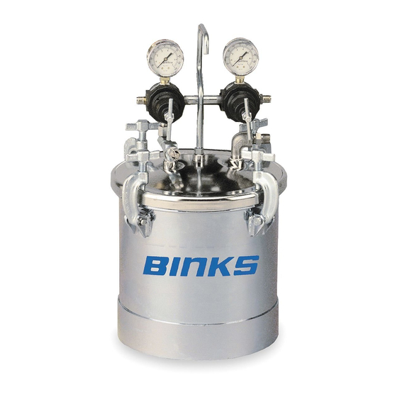
83C PRESSURE TANK
SMALL TANK – UP TO 2.8 GALLONS
IMPORTANT: Read and follow all in-
structions and SAFETY PRECAUTIONS
before using this equipment. Retain
for future reference.
PROP 65 WARNING
CA PROP
65
WARNING: This product
contains chemicals known
to the State of California to
cause cancer and birth
defects or other reproductive harm.
DESCRIPTION
The 83C pressure tanks are designed as a
pressure container to supply liquid mate-
rial at a constant preset pressure up to a
maximum of 80 PSI. All models include a
polyethylene liner. 83C tanks are for light to
medium duty use.
Models:
83C-210: Single regulation (fluid), air inlet/
outlet, fluid outlet, safety valve
83C-220: Dual regulation (air and fluid),
otherwise same as 83C-210
83C-211: Single regulation (fluid), air driven
agitator assembly, fluid outlet, safety valve
83C-221: Dual regulation (air and fluid),
otherwise same as 83C-211
SBBI-21-044-T (10/2015)
Halogenated hydrocarbon solvents
- for example: 1,1,1, - trichloroeth-
ane and methylene chloride - can
chemically react with aluminum
parts and components and cause
an explosion hazard. These solvents
will also corrode the galvanized
tank coating. Read the label or data
sheet for the material. Do not use
materials containing these solvents
with these pressure tanks.
Refer to specifications chart to en-
sure that fluids and solvents being
used are chemically compatible
with the tank wetted parts. Before
placing fluids or solvents in tank,
always read accompanying manu-
facturer's literature.
Air pressure loads that are higher
than design loads, or changes to the
pressure feed tank can cause the
tank to rupture or explode.
• A safety valve protects the tank
from over pressurization. During
each use pull the ring on the safety
valve to make sure it operates freely
and relieves air pressure. If the valve
is stuck, does not operate freely,
or does not relieve air pressure, it
must be replaced. Do not eliminate,
make adjustments or substitutions
to this valve.
• Changes to the air tank will weaken
it. Never drill into, weld or change
the tank in any way.
• The maximum working pressure
of this tank is 80 psi.
1 / 8
Static electricity is created by the
flow of fluid through the pressure
tank and hose. If all parts are not
properly grounded, sparking may
occur. Sparks can ignite vapors
from solvents and the fluid being
sprayed.
If static sparking, or slight shock, is
experienced while using this equip-
ment, stop spraying immediately.
Ground the pressure tank by connect-
ing one end of a 12 gauge minimum
ground wire to the pressure tank and
the other end to a true earth ground.
Local codes may have additional
grounding requirements.
See illustration, page 4, for grounding
and grounding hardware required.
Pressure Relief Procedure
High pressure can cause a serious
injury. Pressure is maintained in
a pressure tank after the system
has been shut down. Before at-
tempting removal of fill plug or
cover, pressure must be relieved
using the following steps:
1. Turn off the main air supply
to the tank.
2. Shut off regulator or remove
air supply line from tank.
3. Bleed off air in the tank by
turning the air relief valve thumb
screw counterclockwise. Wait un-
til all the air has escaped through
the valve before removing the
pressure tank cover or fill plug.
4. Leave the air relief valve open
until you have reinstalled the
cover or fill plug.
EN
Advertisement

Summary of Contents for Binks 83C
- Page 1 The 83C pressure tanks are designed as a using the following steps: pressure container to supply liquid mate- • A safety valve protects the tank rial at a constant preset pressure up to a 1.
-
Page 2: Safety Precautions
SAFETY PRECAUTIONS This manual contains information that is important for you to know and understand. This information relates to USER SAFETY and PREVENTING EQUIPMENT PROBLEMS. To help you recognize this information, we use the following symbols. Please pay particular attention to these sections. Note Important information that tells how to pre- Information that you should pay special... - Page 3 Assemble either single or double air regulator provided with “dual regula- input air pressure 100 P.S.l.) regulator to manifold with 11/16 wrench. tion” tank models (83C-220 or 83C-221). See Spray Gun instructions for opera- INSTALLATION tion of the gun. Mix and prepare material to be used accord- ing to manufacturer’s instructions.
- Page 4 (See Pg. 5 for Breakdown) Air In *5 ---- Street Elbow 1/4" NPT (F) x 1/4" NPT (M) n 6 H-2008 Nipple 1/4" NPT(M) (83C-210 & 83C-220) Fluid Out x 1/4"NPS(M) (83C-211 & 83C-221) 7 HA-57011 Hose Assembly 8 HAV-500 Air Adjusting Valve1/4"...
- Page 5 29 30 31 32 HAR-507 (Ref. No. 10A) & HAR-511 (Ref. No. 10) REGULATOR ASSEMBLIES (HAR-511 shown) Ref. Replacement Description Individual Part No. Parts Req. KK-4977 Repair Kit "O" Ring 45** Spring "O" Ring Valve "O" Ring Diaphragm Assembly PT-410 Air Motor Assembly QS-190 End Cap...
-
Page 6: Service Checks
7. Turn on the air supply to spray gun. 8. Place cloth over air cap on the gun and pull trigger. This will force material back through the hose, into the tank. Binks Solvent Saver 83GZ-5200 can be used to clean hoses and gun fluid passage. - Page 7 No water is needed. and coatings. air lines when no other means (air 29-3100 transformers or regulators) of air Binks (Industrial) pressure regulation is available. 192218 DeVilbiss Automotive Refinishing Ball Valves. VA-542 air inlet shut-off valve. To install, re- PT-78-K10 &...
-
Page 8: Warranty Policy
WARRANTY POLICY Binks products are covered by Finishing Brands one year materials and workmanship limited warranty. The use of any parts or accessories, from a source other than Finishing Brands, will void all warranties. For specific warranty information please contact the closest Finishing Brands location listed below.