Advertisement
Quick Links
MYPIN
TA Series of Temperature Controller
Instruction Manual
Thanks a lot for selecting the product!
Before operating this instrument, please carefully read this
manual and fully understand its contents. If any probroms,
please contact our sales or distributors whom you buy from.
This manual is subject to change without prior notice.
Safety Cautions
★ Make sure the power is off before connecting the wires to avoid
electric shock and strickly follow the connection diagram given out
by the factory.
★ Make sure the power is off when cleaning the instrument.
★ Make sure the instrument works under rated voltage to avoid dam
-age or cause fire.
★ Make sure the OUTPUT RELAY works at the rated load and elec
trical life.The relay may melt or burned or even cause fire if it works
agains its electrical life.
Instalation Notice
★ The instrument should be installed in domestic environment.Please
pre-heat for 15 munites before use.
★ Ambient environment: temp: 0℃(32F)~50℃(122F), humidity:
35%~85%RH.
★ To avoid using the instrument in such environment that full of dust,
explosive gas, vapor, or oil.
★To avoid using the instrument in such environment that full of strong
shock,high interference or other factor.
★ The power cable shoudn't put together with big current cable to
avoid electronmagnetic interference, or use another pip or shield cable.
★ A surge suppressor or noice filter should be installed in case of
noice caused by equipment as motor/transformer/spiral pipe/farrite
cores,etc..
★ The output is active after the power ON fr 10s,please consider this
when configuring cotrol loop.
★The instrument has built-in recoverable fuse to pretect from damage
caused by short-cut circuit. It starts work automatically when
mulfunction is removed.
Applications
TA series temperature controller is available for many TC & RTD
input. It adopts some advanced techonology such as multi digital
filter circuit, autotune PID, fuzzy PID that make it much more precise,
stable. It's widely used in strong anti-interference and automation
systems of mechanism, chemical industrial, chinaware, light industrial,
metallurgy and petroleum chemical industrial. It is also applied to the
production line of foodstuff, packing, printing, dry machine, metal
heat process equipment to control the temperature. simple operation.
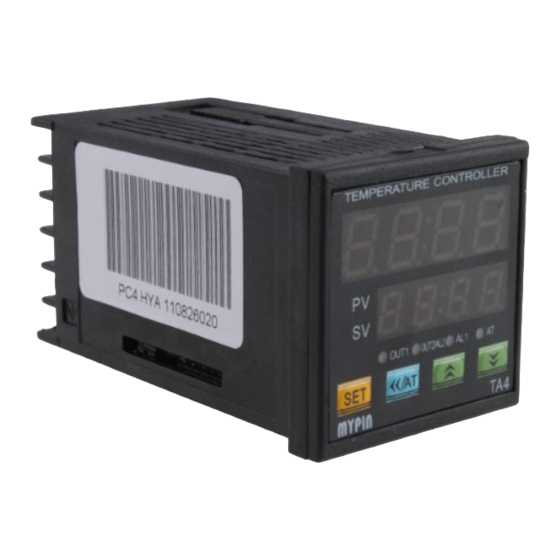
Panel
UNDER DISPLAYING MODE
PV displays current temperaturein F /C
PV
SV displays preset output value
SV
UNDER PRAGRAMMING MODE
PV displays parameter
AT
AL
OUT1
OUT2/AL2
SV displays parameter preset value
/AT
SET
TA
SET UNDER DISPLAY MODE, Access programming mode
UNDER PROGRAMMING MODE,
a. Store selected parameter and index to next parameter (press shortly)
b. Quite programming mode (press>3s)
<</AT UNDER DISPLAY MODE,
a. Access/Quite auto-tuning estate (press>3s ,AT lamp ON/OFF)
b. Access output preset value modification (press shortly)
UNDER PROGRAMMING MODE, shift the digit for modification
Increment selected parameter value or selections
Decrement selected parameter value or selections
Indication lamp:
On: active
Off: inactive
AT:
the auto-tuning operation
AL:
the 1st alarm
OUT1:
Heating/Main control output
OUT2/AL2: the 2nd control output or the 2nd alarm
Specifications
Power supply
90-260V AC/DC 50/60Hz
≤ 5VA
Consumption
-199~1800℃
Display range
0.3%F.S ± 2digit
Accuracy
≤ 300ms
Sampling cycle
Main output
RELAY:normal open AC 250V/3A DC 30V/3A COS¢=1
SSR/LOGIC: 24V DC ± 2V/ 20mA
Alarm
RELAY: normal open AC 250V/3A DC 30V/3A COS¢=1
SSR/LOGIC: 24V DC ± 2V/ 20mA
K
0~999℃/0~1200℃
J
0~999℃ /0~1200℃
T/C
T
-150~400℃ (Special order)
S
0~1600℃
Input
E
0~1000℃
Rt
Pt100
-199~600℃
Cu50
-50~150℃
Others Please mention when ordering
1500V Rms (Between power terminal and the housing)
Withstand voltage strength
Min 50M Ω(500V DC)(Between power terminal and the housing)
Insulation resistance
0~50℃
Environment temperature
-10~60℃
Save temperature
35~85%RH
Environment humidity
≤ 350g
Weight
Models
TA
□□ - □□□□
Input signals:
Default:TC( K,J,E, S) RTD (Pt100,Cu50)
1: 4-20mA 0-10V 0-75mV
2: 4-20mA 0-10V Pt100
F: others (indicate when ordering)
AL1: R: RELAY
S: SSR/Logic
OUT2/AL2:
R: RELAY S: SSR/Logic N: None
OUT1: R: RELAY
S: SSR/Logic
I: 4-20mA
V: 0-10V
Power Supply: Default: 90-260V AC/DC
E: 24VDC or 18-30V AC/DC
Dimension: 4: 48H × 48W 6: 48H × 96W
7: 72H × 72W
8: 96H × 48W 9: 96H × 96W
TA series of temperature controller
Mounting and Sizes
A
↑
+
+
↑
D
+
+
C
↑
F
E
G
H
Sizes
A
B
C
D
E F
Model
44.5+0.5
45+0.5
65
65
48
48
TA4
43.5+0.5
91+0.5
65
115
48
96
TA6
91+0.5
91+0.5
115
115
96
96
TA7
91+0.5
43.5+0.5
65
115
96
48
TA8
67.5+0.5 67.5+0.5
95
95
72
72
TA9
Parameter Setting
Press SET or
and
>3s to enter the parameter setting menu.
A: Press SET to select the parameter to be changed,
B: Press <</AT key to select one of the digits of the setting(value) for
change.
C: Press
/ to make a change.
D: Press SET to save and move to the next parameter.
NOTE: SV window display convertsion. Under display mode, press
SET to convert display value for OUT or AL1.
Power on
Self-check
All LED on
↓
3S
Temp. unit
-
Input type
↓
3S
N: None
Max input limit
Min input limit
↓
3S
Current Temp
N: None
Preset output value
↓
/AT
Confirm
Modify
Shift and flashes
↓
Stop flashing
Press
SET
>3S
B
↓
AL1(Alarm setting)
range: –1999-9999
↓
SET
AM1(Alarm mode):
0: Deviation HI alarm 1: Deviatian
LO alarm 2: Absolute value HI alarm
3: Absolute value LO alarm 4: Section
outside alarm 5: Section inside alarm
↓
6: TC broken alarm ,The factory setting is 2
SET
AL2 set range: –1999-9999.
①
↓
G
H
AL2 mode: The same as AL1.
8
80
↓
12
80
Range: ± 100.Display value
12 100
PV = Measured value - PVF
12
80
↓
12 100
Input signal selection TC: K, J, T,E, S
RTD: Pt100, Cu50
The factory setting is K
↓
Proportional band (%) range 0.1-3600.
If P=OFF, it means ON/OFF control
↓
Integral time range 0.1-3600. I=OFF means
cancel integral time.
↓
Proportional band (%) range 0.1-3600.
If P=OFF, it means ON/OFF control
Advertisement

Summary of Contents for AGPtek TA4
- Page 1 MYPIN Power on Panel Models Self-check □□ - □□□□ Input signals: TA Series of Temperature Controller All LED on UNDER DISPLAYING MODE ↓ Default:TC( K,J,E, S) RTD (Pt100,Cu50) PV displays current temperaturein F /C Instruction Manual 1: 4-20mA 0-10V 0-75mV Temp.
- Page 2 ↓ Application examples Note: TA6/8 Control directions: 1.When the user operate the instrument at first time, please 1.Relay output control (forTA4-RNR) 90-260V AC/DC HEAt: heating COOL: cooling operate according to the processes of this instruction ↓ manual. Let the instrument in autotuning, if the Control hysteresis, range: ±...