Advertisement
Quick Links
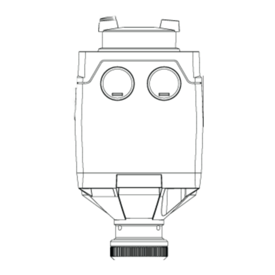
SAS61 Series Electronic Valve Actuators
Product Description
The SAS actuators require a 24 Vac or 24 Vdc, Class
2, supply and a 0 to 10 Vdc or 4 to 20 mA signal to
control Powermite 599 Series terminal unit valves with
7/32-inch (5.5 mm) stroke. In the SAS61.33U, a
mechanical spring returns the valve to its normal
position when there is no power supply.
Warning/Caution Notations
WARNING:
CAUTION:
Product Numbers
SAS61.03U – Non-spring Return (Fail-in-place)
actuator
SAS61.33U – Spring Return (Fail-safe) actuator
Required Tools
•
#2 Phillips or flat-blade screwdriver
•
Flat blade calibration screwdriver (3 mm) for
wiring connections
•
Wire cutter/stripper
Estimated Installation Time
•
12 minutes for wiring a factory-installed
actuator.
•
30 minutes for field replacement of an
actuator.
Prerequisites
WARNING:
Disconnect the controller power before
replacing the actuator.
Item Number: 129-612, Rev. AA
Personal injury/loss of life may
occur if you do not perform a
procedure as specified.
Equipment damage, or loss of
data may occur if you do not
follow the procedures as
specified.
Installation Instructions
Document No. 129-612
WARNING:
If mounting the actuator to a valve
already in line, either close the shut-off
valves in the piping (upstream first,
then downstream) or switch off the
pump to allow the differential pressure
in the valve to drop.
Mounting
Figure 1 shows acceptable actuator mounting positions
for water applications. The recommended mounting
position of the actuator for low pressure steam
applications is between 45° and horizontal.
Figure 1. Acceptable Mounting Positions.
Installation
If you are mounting an actuator on a new valve, begin
with the instructions, Mounting an Actuator to a Valve.
Remove Actuator from Valve
1.
Remove actuator cover screws using either a
No. 2 Phillips or a No. 2 flat-blade screwdriver and
detach actuator cover.
2.
Identify and disconnect wires.
3.
Replace actuator cover. Use cover screws to
secure actuator cover in place.
4.
Loosen coupling piece.
5.
Remove actuator from valve.
January 19, 2016
Page 1 of 3
Advertisement

Related Manuals for Siemens SAS61.03U


Summary of Contents for Siemens SAS61.03U
- Page 1 Equipment damage, or loss of CAUTION: data may occur if you do not follow the procedures as specified. Product Numbers SAS61.03U – Non-spring Return (Fail-in-place) actuator SAS61.33U – Spring Return (Fail-safe) actuator Figure 1. Acceptable Mounting Positions. Installation Required Tools •...
- Page 2 Terminal connection G is 24 Vac HOT, not remove the protective plastic cap from the valve ground. stem. 2. On the SAS61.03U Actuator, turn the manual- CAUTIONS: • positioning knob counterclockwise to its end G0 and G must be properly wired for point.
- Page 3 January 19, 2016 Dimensions ► ►► Inches 21.9 71.1 29.9 21.8 Figure 4. SAS61.03U Actuator Dimensions. ► ►► Inches 21.9 84.6 29.9 21.8 Figure 5. SAS61.33U Actuator Dimensions. Information in this publication is based on current specifications. The company reserves the right to make changes in specifications and models as design improvements are introduced.