Advertisement
Quick Links
08-PT76XX-B0-EM, 04/07/2011
TEMPERATURE
CONTROLLER
PV
1
SV
2
3
4
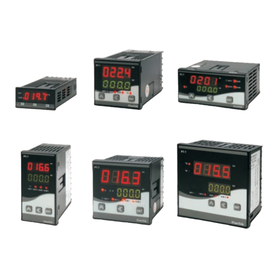
PT-7610
PT-7620
PT-7630
6
7
8
5
1
Process value,and functions display.
PT-7631
PT-7640
PT-7650
(Red 7-segment)
2
Setting value,and parameters display.
Content of the packaging
(Green 7-segment)
Noumenon
Washer
3
Control output indicator
Back cover
User' s manual
4
Alarm indicator.
Bracket (2pcs)
5
Unit indicator Lighted:BC Unlighted:BF.
Thank you for please read the User' s manual first before buying
Fine-Tek products and using and is familiar with product
6
"Up" key: addition and mode change.
performance and every function, please keep the user' s manual
7
"Shift" key: position shift.
so that consult in future. Modbus communication can be
downloaded from
http: //www.fine-tek.com
8
"Enter" key: confirmation.
SPECIFICATIONS
DC: 20~36Vdc ※Except PT-7610
1. Really lock the end Terminals screw, if the screw has not been locked but
Power Supply
lost by causing the fire or mechanical breakdown.
AC: 100~240Vac 50/60Hz
2. Please don't be using this product and having places where we can fire
Power Consumption
7A Max.
gas, cause the risk of exploding by the fact that it may.
Output:
SPST- 3A/250Vac
3. The life-span of the relay must depend on the user's usage, the use of
Relay
the relay must be in specified load and life-span of electric apparatus that
(Life Time:100,000 times)
it labels, if the use of the relay exceeds its life-span, the danger that may
Pulse
melt or cause the fire in the contact of the relay.
12Vdc (NPN), 20mA Max.
(Driven by SSR)
4. Don't disassemble, repair or revise the products without authorization,
this measure may cause the short circuit of the electric apparatus,
Analog
4~20mA, 0~10Vdc (600W Max.)
trouble or fire.
Alarm Output
SPST-NO, 3A/250Vac
5. Don't drop inside products by chip or chip of wire metal, will cause the
short circuit and account or fire.
Alarm Delay Time
0~99s
Alarm Output
0~9999
Hysteresis Adjustment
Communication
RS485 Output
Interface
Use the product within the ratings specified for submerging in water and
Working Temperature
0~50BC (20~85% RH)
exposure to oil.
Do not use the product in locations subject to vibrations or shocks. Using
Cycle Time of
0.5~999.9s
Output Control
the product in such locations over a long period may result in damage
due to stress.
ON/OFF or PID +Fuzzy(Auto Tuning)
Control Method
Do not use the product in locations subject to dust, corrosive gasses, or
Input Compensation
-1999~9999
direct sunlight.
Sampling Time
250 ms
Separate the input signal devices, input signal cables, and the product
Accuracy
0.3%A1digit
from the source of noise or high-tension cables producing noise.
Separate the product from the source of static electricity when using the
product in an environment where a large amount of static electricity is
produced (e.g., Forming compounds, powders, of fluid materials being
ERROR MESSAGES
transported by pipe).
Organic solvents (such as pain thinner), as well as very acidic or basic
Display over scale
solutions might damage the outer casing of the Temperature controller.
Display under scale
Store at the specified temperature. If the Temperature controller has
been stored at a temperature of less than -10BC, allow the Counter to
Over measure range
stand at room temperature for at least 3 hours before use.
Wait 30 minutes after power on before calibration .
Under measure range
Sensor break
DESCRIPTION OF PARAMETERS
LOCK
You can set a hysteresis around the set
Control output
point to prevent chattering
hysteresis
In PID control, I=0, PV=SV, reset the control
Manual reset
output to "
" value
This function should be used the PV display
value may fluctuate greatly,for example, when
PV input filter
the measured input signal contains noise. If a
larger time constant is set, the filter can
remove more noise.
The cycle time is the period of on/off repetitions of a relay
or voltage pulse output in time proportional PID control.
Cycle time
The ratio of the ON time to the cycle time is proportional to
the control output value. If output for the relay, setting has
to be more than 15.
Direction of relay
You can set the mode of function lists which
Function list
can be displayed and edited.
lock
FRONT PANEL
DIMENSION / PANEL CUTOUT
unit: (mm)
TERMINAL ARRANGEMENT
Please inspect the specification of the power.
Don't connect the end Terminals not used.
Propose that the signal line uses AWG 18~24
to enclose the isolate wire, the main power
cable and relay export the contact and use
AWG 25~30.
OUT1
OUT2
ALM
LC
F
n eT e k
l
Main
Sub Item
Data Range
Item
OFF~2
-1999~9999
0000~9999
00~99
-1999~9999
Please strictly observe the following instructions, it can
guarantee this safe operation in anticipated cases of
0000~9999
controller:
00~99
-1999~9999
0~3
-1999~9999
-1999~9999
-1999~9999
-1999~9999
-1999~9999
-1999~9999
FUNCTION LOCK
LOCK
PT-7610 48mm(W)x24mm(H)x98.5mm(D)
PT-7620 48mm(W)x48mm(H)x101mm(D)
48
8
90.5
48
9
92
OUT
BC
24
ALM
BF
PV
21.6
48
SV
44.8
l
F
n eT e k
OUT1
OUT2
ALM
LC
58 min.
F
n eT e k
l
55 min.
46 min.
+0.6
24
-0
67 min.
48
+0.8
-0
45
+0.6
-0
45
+0.6
-0
G
mA
F
B
b
A
Control output : DC V/ mA
NO
12VDC
output
Relay output
RTD
Voltage pulse
ALM
Retransmit output : DC V/ mA
F
G
TC/V
F
F
4
4
4
OUT1
DC V/ mA
12VDC
7
8
9
10
11
12
3
3
3
G
G
F
1
2
3
4
5
6
RS
18
6
100~240V AC
485
11
G
17
5
RTD
F
RS-485
NO
F
G
100~240V AC
B
10
16
4
OUT
EXC
TC/V
OUT1
F
24V
9
15
3
mA
b
G
G
F
A
8
14
2
F
G
OUT2
ALM
Control output : DC V/ mA
12VDC output
Relay output
13
1
Voltage pulse
G
Retransmit output : DC V/ mA
F
F
4
4
4
OUT
DC V/ mA
12VDC
3
3
3
F
F
G
G
14
14
14
DC V/ mA
OUT2
12Vdc
13
13
13
G
G
FUNCTION LIST
Main
Default Value
Describe
Sub Item
Data Range
Default Value
Item
0
Alarm soft activation
0~9999
3
P Value
Alarm Relay Position 1
0~9999
200
I Value
0
0
Alarm Relay Hysteresis 1
0~9999
20
D Value
0.0~100.0
0
Manual Reset
00
SEC
Alarm Relay Delay Time 1
Alarm Relay Direction 1
1~50
1
Input digital Filter
Alarm Relay Style 1
Hold temperature over room tempereture
Alarm follow the action of out1
Hold temperature below room tempereture
Alarm follow the action of out2
Heater is controlled by out1
Alarm Relay Position 2
Cooler is controlled by out1
0
0
Alarm Relay Hysteresis 2
Heater is controlled by out2
Alarm Relay Delay Time 2
Cooler is controlled by out2
00
SEC
Alarm Relay Direction 2
Control output direct/reverse operation 1
Alarm Relay Style 2
Control output direct/reverse operation 2
Alarm follow the action of out1
0.5~999.9
15 sec
Cycle Time 1 (Second)
Alarm follow the action of out2
0.5~999.9
15 sec
Cycle Time 2 (Second)
0
Set Value SV
Control output Hysteresis 1
0~9999
0000
0
Decimal point set
0~9999
0000
Control output Hysteresis 2
9999
Scale upper limit value
OFF
Deadband control
0
Scale lower limit value
-1999~9999
0
Deadband parameter of Heater
9999
Limit Hi (Max. Value of SV range)
-1999~9999
0
Deadband parameter of cooler
-1999
Limit Lo (Min. Value of SV range)
0~9999
0
Loop break alarm
Operation
ON/OFF
A:
B:
C:
D:
E:
F:
G:
OFF
Auto Tuning
K:
L:
M:
N:
O:
P:
Q:
0
PV input bias
U:
V:
W:
X:
Y:
Z:
0
SV offset value during auto tuing
Except TC/RTD input
LOCK
PT-7630 96mm(W)x48mm(H)x92.5mm(D)
PT-7631 48mm(W)x96mm(H)x92.5mm(D)
10
48
82.5
10
96
82.5
96
91.8
48
44.8
102 min.
67 min.
67 min.
45
+0.6
-0
102 min.
92
+0.8
-0
92
+0.8
-0
45
+0.6
-0
Control output : DC V/ mA
12VDC output
Control output : DC V/ mA
12VDC output
Relay output
Relay output
Retransmit output : DC V/ mA
Voltage pulse
Retransmit output : DC V/ mA
Voltage pulse
NC
8
8
F
F
NC
F
F
OUT1
7
7
7
OUT1
7
NO
7
OUT1
DC V/ mA
12VDC
OUT1
NO
7
OUT1
DC V/ mA
12VDC OUT1
6
6
6
6
COM
6
G
G
F
F
COM
6
G
G
OUT2
F
F
5
5
5
5
OUT2
5
DC V/ mA
12VDC OUT2
OUT2
5
4
4
DC V/ mA
12VDC OUT2
OUT2
4
G
G
4
4
4
G
G
ALM 1
F
100~240 V AC
20
10
100~240V AC
ALM 2
EXC24V
19
9
OUT 1
OUT 2
G
8
10
9
8
7
6
5
4
3
2
1
F
17
7
OUT1
RS485
16
G
6
RTD
5
G
OUT2
TC/V
B
14
4
F
mA
b
13
3
20
19
17
16
14
13
12
11
ALM
ALM
A
12
2
F
G
2
1
G
G
TC/V
G
11
1
EXC24V
RS485
RTD
B
b
A
G
mA
F
Main
Describe
Sub Item
Data Range
Default Value
Describe
Item
0~255
Device ID No.
BaudRate:600
BaudRate:1200
BaudRate:2400
BaudRate:4800
BaudRate:9600
BaudRate:19200
8 data bit ; No Parity ; 1 Stop Bits
8 data bit ; No Parity ; 2 Stop Bits
8 data bit ; Odd Parity ; 1 Stop Bits
8 data bit ; Even Parity ; 1 Stop Bits
Hex
Ascii
Lock Label 0
Lock Label 1
Lock Label 2
Lock Label 3
0~999
0
Password protection
Quick SV setup protection
Allow entry manual mode
EEPROM protection
Default to factory setting
H:
I:
J:
0~99
10
Sceen return time (S)
R:
S:
T:
SAFETY SETUP
LB00:
Parameter Open
LB01:
Alarm, SV, and CTRL setup only
LB02:
SV setting only
LB03:
Lock setup only, other parameters are not
available for setup
PARAMETERS OF HYSTERESIS LIST
Heater
Cooler
Heater
Disable
Enable
Disable
SV+
SV+
Disable
Disable
Enable
SV
SV
Disable
Disable
Enable
SV+
SV+
Enable
Disable
Enable
<0,
>0
>0,
Disable : Inhibit output
Enable : Enable control output to follow PID/ON-OFF
control algorithm
PT-7640 72mm(W)x72mm(H)x80.5mm(D)
PT-7650 96mm(W)x96mm(H)x83mm(D)
96
8
75
72
10
70.5
72
67
96
91
90 min.
102 min.
90 min.
114 min.
68
+0.7
92
+0.7
-0
-0
68
+0.7
92
+0.7
-0
-0
Control output : DC V/ mA
12VDC output
Control output : DC V/ mA
12VDC output
Relay output
Relay output
Retransmit output : DC V/ mA
Voltage pulse
Retransmit output : DC V/ mA
Voltage pulse
F
F
F
F
24
24
OUT1
24
70
70
OUT1
70
OUT1
DC V/ mA
12VDC
OUT1
DC V/ mA
12VDC
OUT1
OUT1
23
23
23
69
69
69
G
G
G
G
F
F
F
F
22
22
OUT2
22
53
53
OUT2
53
OUT2
DC V/ mA
12VDC OUT2
DC V/ mA
12VDC OUT2
OUT2
21
21
21
54
54
54
G
G
G
G
49
61
RS485
EXC24V
50
62
F
16
24
8
OUT 1
RS485
100~240V AC
51
63
G
15
23
7
ALM2
52
64
RTD
14
22
6
OUT 2
G
53
65
TC/V
13
21
5
B
OUT 2
54
66
12
20
F
4
mA
b
ALM1
11
19
3
43
55
67
F
ALM1
A
10
18
2
mA RTD
44
56
68
G
F
ALM2
EXC24V
B
9
17
1
45
57
69
G
OUT 1
b
46
58
70
47
59
71
A
100~240V AC
48
60
72
TC/V
Special mean entry method
Measurement
Input Type
Indication
Range
K Type
(default)
-200~1370BC
K Type
-128.0~500.0BC
J Type
-200~1200BC
J Type
-128.0~500.0BC
T Type
-200~400BC
TC
T Type
-128.0~400.0BC
(BC)
E Type
-200~800BC
R Type
0~1760BC
S Type
0~1760BC
B Type
0~1820BC
N Type
-200~1300BC
PT Type
-200~850BC
PT Type
-199.9~850.0BC
RTD
(BC)
JPT Type
-200~500BC
JPT Type
-199.9~500.0BC
K Type
-328~2498BF
K Type
-199.9~932.0BF
J Type
-328~2192BF
J Type
-199.9~932.0BF
T Type
-328~752BF
TC
T Type
-199.9~752.0BF
(BF)
E Type
-328~1472BF
R Type
32~3200BF
S Type
32~3200BF
B Type
32~3308BF
N Type
-328~2372BF
PT Type
-328~1562BF
PT Type
-199.9~999.9BF
RTD
(BF)
JPT Type
-328~932BF
JPT Type
-199.9~932.0BF
0~50mV
-1999~9999
0~1V
-1999~9999
0~5V
-1999~9999
V
1~5V
-1999~9999
0~10V
-1999~9999
2~10V
-1999~9999
0~20mA
-1999~9999
mA
4~20mA
-1999~9999
Type R and S A8BC for 0 to 500BC
Type B accuracy is not guaranteed for 0 to 600BC
Special menu entry method
Cooler
Main
Key Combinations
Describe
Notes
Item
Enable
Enable
Reference list of
Press
and
Input Signal Option
input signal
Enable
hold for 3 seconds
Disable
Reference Program
Press
5 seconds
Manual control
<0
setting flowchart
Advertisement

Related Manuals for FineTek PT-7610

Summary of Contents for FineTek PT-7610
- Page 1 //www.fine-tek.com "Enter" key: confirmation. SPECIFICATIONS FUNCTION LIST Special mean entry method DC: 20~36Vdc ※Except PT-7610 1. Really lock the end Terminals screw, if the screw has not been locked but Power Supply Main Main Main lost by causing the fire or mechanical breakdown.
- Page 2 PROGRAM SETTING FLOWCHART Power PV, SV Operation Heater is controlled by out 2 Press hold for 3 seconds Press at least 5sec to enter Alarm soft activation Set Value SV Device ID No. Lock Label Cooler is controlled by out 2 ONOFF/PID Manual control Control output direct/ reverse...