Table of Contents
Advertisement
MINI HiFi COMPONENT SYSTEM
RXD-A55/A75
SERVICE MANUAL
(XD-A55/A75)
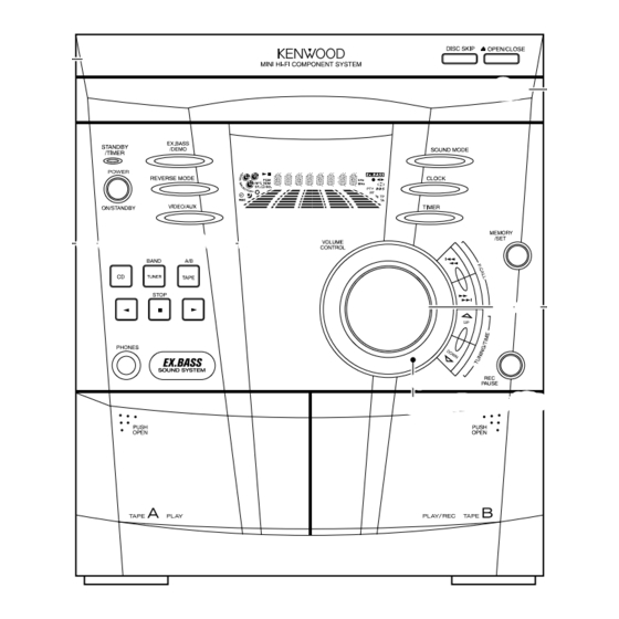
Panel ass'y
(A60-2091-08)
Front glass *
(B10-)
In compliance with Federal Regulations, following are repro-
duction of labels on, or inside the porduct relating to laser prod-
uct safety.
© 2001-4/B51-5713-00 (K/K) 1382
* Refer to parts list on page 33.
KENWOOD-Crop. certifies this equipment conforms to DHHS
Regulations No.21 CFR 1040. 10, Chapter 1, subchapter J.
DANGER : Laser radiation when open and interlock defeated.
AVOID DIRECT EXPOSURE TO BEAM.
Panel(CD)
(A60-2090-08)
Knob(VOLUME)
(K27-2470-08)
Dress ring
(A21-3957-08)
70%
Advertisement
Table of Contents

Related Manuals for Kenwood RXD-A55


Summary of Contents for Kenwood RXD-A55
- Page 1 Dress ring (A21-3957-08) * Refer to parts list on page 33. KENWOOD-Crop. certifies this equipment conforms to DHHS In compliance with Federal Regulations, following are repro- Regulations No.21 CFR 1040. 10, Chapter 1, subchapter J. duction of labels on, or inside the porduct relating to laser prod- uct safety.
-
Page 2: Table Of Contents
RXD-A55/A75 CONTENTS / ACCESSORIES Contents CONTENTS / ACCESSORIES ........2 PC BOARD .............. 16 EXTERNAL VIEW ............3 SCHEMATIC DIAGRAM .......... 23 DISASSEMBLY FOR REPAIR........4 EXPLODED VIEW ............31 BLOCK DIAGRAM ............9 PARTS LIST..............33 CIRCUIT DESCRIPTION ..........11 SPECIFICATIONS ............37 ADJUSTMENT ............14 Accessories... -
Page 3: External View
RXD-A55/A75 EXTERNAL VIEW Cabinet(TOP) (A02-3014-08) ANTENNA FM Antenna 75Ω (E70-0145-08) Pin ass'y AM LOOP (E40-8933-08) VIDEO Pin jack /AUX (E63-1219-08) SPEAKERS Lock terminal board (E70-0144-08) AC power cord bushing (J42-0351-08) AC power cord (E30-7222-08) -
Page 4: Disassembly For Repair
RXD-A55/A75 DISASSEMBLY FOR REPAIR Caution on Disassembly Follow the below-mentioned notes when disassembling (A1)x2 Top Cabinet the unit and reassembling it, to keep it safe and ensure ø3x12mm excellent performance: 1. Take cassette tape and compact disc out of the unit. - Page 5 RXD-A55/A75 DISASSEMBLY FOR REPAIR (L2) x1 CLAMP LEVER Turntable CAM GEAR RIB Disc Tray (L1) x2 Figure 8-1 (F1)x1 (F1)x1 ø3x6mm ø3x10mm CD Player Unit Figure 8-4 (E2)x2 (E3)x1 (M1) x3 (E4)x1 Power Supply Main PWB (E2)x1 (M1) x3 (F2)x1...
- Page 6 RXD-A55/A75 DISASSEMBLY FOR REPAIR (P2) x3 Mechanism Loading Motor (P1) x1 (P1) x1 (Q1) x5 Figure 9-1...
-
Page 7: Removing And Reinstalling The Main Parts
RXD-A55/A75 DISASSEMBLY FOR REPAIR REMOVING AND REINSTALLING THE MAIN PARTS TAPE MECHANISM SECTION TAPE2 Perform steps 1 to 7 and 9 of the disassembly method to Record/Playback remove the tape mechanism. Head How to remove the record/playback and erase heads (TAPE 2) (See Fig. 10-1) 1. - Page 8 RXD-A55/A75 DISASSEMBLY FOR REPAIR CD MECHANISM SECTION Perform steps 1, 2, 3, 11 and 14 of the disassembly method to remove the CD mechanism. How to remove the loading motor Loading Moter (See Fig. 11-1) 1. Bend the hooks (A1) x 5 pcs., to remove the loading motor.
- Page 9 FL701 DISPLAY IC301 T302 FM IF CF303 CNP301 BF301 ZD351 TA7358AP B.P.F FM FRONT END T351 AM IF CF352 Q701-703 X351 Q710-712 RX701 456kHz REMOCON JOG701 SENSOR 67-78 IC302 P-IN VLOAD L312 T301 UPD 780206 80-89 FM RF FM OSC SYSTEM LA1832S 90-92...
- Page 10 33.8688MHz CONSTANT RFVDD VOLTAGE CNP7 VVDD R-CH +3.3V AGND PICK UP UNIT ADAVDD L-CH LCHO MAIN DGND SECTION LVSS XVDD RVSS LVDD RCHO RVDD FIN1 CONT4 CNP8 FIN2 LC78645E SERVO/SIGNAL TIN1 CONTROL CONT3 TIN2 CONT2 DISPLAY 5 DI SECTION CD RES CLAMP SW OC.
-
Page 11: Circuit Description
RXD-A55/A75 CIRCUIT DESCRIPTION 1. Port Description of Microprocessor Port No. Port Name Function POWER SUPPLY(+5V) -20dB ATT -20dB ATTENUATION NO USE/DSA STB T BIAS DECK BIAS CONTROL T T1/T2 DECK T1/T2 CHANGE OVER REC/PLAY DECK RECORDING/PLAYBACK CHANGE OVER RES OUT... - Page 12 RXD-A55/A75 CIRCUIT DESCRIPTION Port No. Port Name Function DECK REVERSE RECORDING SWITCH INPUT MIC IN OPEN MP3 LED MP3 LED CONTROL DESTOUT DISCRIMINATION PORT FOR DESTINATION STANDBY LED STANDBY LED CONTROL KARAOKE LATCH OPEN 62~66 NO USE P22~P19 FL DISPLAY CONTROL PORT...
-
Page 13: Adjustment
RXD-A55/A75 CIRCUIT DESCRIPTION 1. Test Mode 1-1 How to Set up the Test Mode • During POWER OFF mode, push below each 2 keys and [POWER] key. Then go to each TEST MODE. KEYS TEST MODE [ POWER ] [ SOUND ] + [ CD ]... - Page 14 RXD-A55/A75 CIRCUIT DESCRIPTION 1-3-2 Software Reset Function: Software RESET. All the function condition will be initialize. It will jump to A operation in case of power ON. After display "CLEAR ALL", power will off. Forwarding condition set for CD changer.
- Page 15 RXD-A55/A75 CIRCUIT DESCRIPTION 1-3-4 CD Changer Aging Test Mode START " " KEY TRAY OPEN IF THE ERROR OCCURS, GO TO ERROR MODE DISC SKIP DISC SKIP DISC SKIP TRAY CLOSE DISC X PLAY DISC SKIP DISC Y PLAY DISC SKIP DISC Z PLAY 2.
-
Page 16: Mechanism Section
RXD-A55/A75 ADJUSTMENT • Tape Speed MECHANISM SECTION • Driving Force Check Adjusting Specified Instrument Test Tape Value Point Connection Torque Meter Specified Value 3,000 ± Normal MTT-111 Variable Speaker Play: TW-2111 Tape 1: Over 80 g speed Resistor in 30 Hz... - Page 17 RXD-A55/A75 ADJUSTMENT CD ERROR CODE DESCRIPTION CD SECTION Error State Code • Adjustment [Servo System Error] Since this CD system incorporates the following automatic 0001 Cannot detect Pickup-in SW adjustment functions, readjustment is not needed when 0002 DSP access error replacing the pickup.
-
Page 18: Pc Board
PC BOARD (Component side view) CD SECTION CNP8 CNP5 CNP7 BI1-A CNP4 CNP3 Refer to the schematic diagram for the value of resistors and capacitors. -
Page 19: Schematic Diagram
PC BOARD(Component side view) DISPLAY SECTION J700 LED709 C704 39 38 LED700 SW704 SW719 R804 R760 Q706 R805 D700 J717 R761 D701 R762 J718 Q707 EX-BASS J709 D702 R763 J719 J710 R764 Q708 D703 J722 J720 R765 J724 Q709 RD16 SW703 J725 J723... - Page 20 PC BOARD(Component side view) MAIN SECTION Q122 C146 R156 R140 WT902 J108 R146 JK670 JK670 R132 R158 R154 C124 C140 C135 R142 C136 R145 Q121 C141 C134 C145 J679 MJ101 R378 R141 X352 J678 R126 R135 R388 R136 J673 J107 J677 C396 R138...
- Page 21 PC BOARD(Component side view) POWER SECTION CNP901 J921 R929 L901 Q903 C927 Q905 J919 C929 J930 Q904 R953 R917 J931 C930 R931 C958 R932 C928 R954 R941 R930 J933 C915 L902 C918 C917 J934 R942 J935 J910 RL901 J908 R906 R909 R907 R918...
- Page 22 20 21 22 23 24 25 26 11 10 8 7 6 5 4 3 2 C607, R623, MODEL NAME CLK 24 IC301 : TA7358AP VDD 23 RXD-A55 0.12 IC302 LC72131 C605 LA1832S RXD-A75 4.7K IC303 4.7u50 IC601 : LC75341 VREF 22 5.0V...
- Page 23 JK601 TUNER/MAIN SECTION R633 Lch 1 CD SECTION AUX IN 5.0V 3.2V R634 Rch 2 10.0V C602 22u50 LASER BI11 DRIVER C614 R608 0.022 10u50 A GND PICKUP UNIT CNP8 CD GND CNS1B CNS1A CNP1 CD +B 5.0V C610 R606 VREF 0.12 3.9K...
- Page 24 FH807 (1G-8G) R741 F805 -59.8V D810 C901, R909 5A 125V MODEL NAME T801 R950 D703 D809 D810 D809 R771 R740 RXD-A55 L07-3118-08 3300u63 1.5K D3SBA60F TS6B04GM FH810 FH809 RXD-A75 L07-3116-08 3300u71 1.2K TS6B04GM D10XB60F R766 F806 26.8V R739 2A 125V -26.8V...
- Page 25 VOLUME DOWN VR701 RD04 680 RD05 820 RD06 1K RD07 1.5K RD08 2.2K SW705 SW706 SW707 SW708 SW709 SW710 TAPE TUNER RXD-A75/A55 RD01 680 RD02 820 RD03 1K SW701 SW702 SW703 SW704 RXD-A55/A75 POWER VIDEO REVERS X-BASS MODE +12V Y39-3960-10...
-
Page 26: Exploded View
RXD-A55/A75 EXPLODED VIEW (CD MECHANISM) AL SCREW : N09-5335-08 AM ø3x8 : N09-5332-08 AN ø2.6x6 : N32-2606-46 AQ ø2x3 : N30-2003-46 AR WASHER : N19-1435-05 AS ø2x5 : N86-2005-46 PWB-F PWB-B PWB-C Parts with exploded numbers larger than 700 are not supplied. - Page 27 3x10 N09-5331-08 SCREW N09-5334-08 SCREW N09-5335-08 φ 3x10 N09-5338-08 φ N09-5343-08 φ N09-5346-08 φ SPEAKER 3x14 N09-5347-08 TERMINAL N09-5348-08 SO901 φ N09-5349-08 φ 3x10 N09-5222-08 φ POWER 3x10 N09-5337-08 TRANS 2.6x4 N09-5336-08 T801 DISP DISC SKIP SW720 SW721 RPEH RXD-A55/A75...
- Page 28 I : Malaysia Y : PX(Far East,Hawaii) T : England E : Europe G : Germany V : China(Shanghai) 5 : RXD-A55 7 : RXD-A75 Y : PX(Far East,Hawaii) T : England E : Europe G : Germany V : China(Shanghai)
- Page 29 I : Malaysia Y : PX(Far East,Hawaii) T : England E : Europe G : Germany V : China(Shanghai) 5 : RXD-A55 7 : RXD-A75 Y : PX(Far East,Hawaii) T : England E : Europe G : Germany V : China(Shanghai)
- Page 30 I : Malaysia Y : PX(Far East,Hawaii) T : England E : Europe G : Germany V : China(Shanghai) 5 : RXD-A55 7 : RXD-A75 Y : PX(Far East,Hawaii) T : England E : Europe G : Germany V : China(Shanghai)
- Page 31 I : Malaysia Y : PX(Far East,Hawaii) T : England E : Europe G : Germany V : China(Shanghai) 5 : RXD-A55 7 : RXD-A75 Y : PX(Far East,Hawaii) T : England E : Europe G : Germany V : China(Shanghai)
- Page 32 I : Malaysia Y : PX(Far East,Hawaii) T : England E : Europe G : Germany V : China(Shanghai) 5 : RXD-A55 7 : RXD-A75 Y : PX(Far East,Hawaii) T : England E : Europe G : Germany V : China(Shanghai)
- Page 33 I : Malaysia Y : PX(Far East,Hawaii) T : England E : Europe G : Germany V : China(Shanghai) 5 : RXD-A55 7 : RXD-A75 Y : PX(Far East,Hawaii) T : England E : Europe G : Germany V : China(Shanghai)
-
Page 34: Specifications
RXD-A55/A75 SPECIFICATIONS XD-A55 Main Unit [CD player section] [Amplifier section] Laser wave length ......770 to 795 nm Laser power class ........1 (FDA) Rated power output Wow & Flutter ..Less than unmeasurable Limit watts per channel minimum RMS, both channels driven, at 6 Ω... -
Page 35: Parts List
KENWOOD ELECTRONICS GULF FZE KENWOOD ELECTRONICS U.K. LIMITED P.O.Box 61318, Jebel Ali, Dubai, U.A.E. KENWOOD House, Dwight Road, Watford, Herts., WD1 8EB., United Kingdom KENWOOD ELECTRONICS SINGAPORE PTE LTD. KENWOOD ELECTRONICS BELGUM N.V. No. 1 Genting Lane #02-02, KENWOOD Building, Singapore, 349544 Meachelsesteenweg 418, B-1930 Zaventem, Belgium KENWOOD ELECTRONICS (MALAYSIA) SDN BHD.