Advertisement
Quick Links
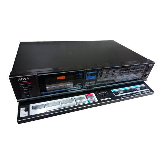
A I W A
SERVICE MANUAL
STEREO CASSETTE
OECK
T
Y
P
E
.
H
B
Type
Stereo cassette tape deck
Track format
4 tracks 2 channels
Power supply
AD-R450 E, Z
AC 220 V, 50/60 Hz
AD-R450 K, G
AC 240 V, 50/60 Hz
AD-R450 U, C
AC 120 V, 60 Hz
A D -R 450 H, H U , HJ
AC 120 V/220 V-240 V switchable,
50/60 Hz
Power
consumption
15 W
Frequency
response
METAL tape:
C r0 2 position tape: 20— 17,000 Hz
NORMAL tape:
Signal-to-noise
ratio
73 dB (METAL tape DOLBY C NR
ON)
Wow and flutter
According to DIN 45 500
0.04% (WRMS)
Tape speed
4.8 cm/sec. (1 -7/8 tps)
Rewind time
70 sec. (C-60)
Fast forward time
70 sec. (C-60)
H
U
B
H
J B
C
j
j
j
SPECIFICATIONS
2 0 -1 8 ,0 0 0 Hz
2 0 -1 6 ,0 0 0 Hz
0.1%
M
O
D
E
L
I M O .
AD-R450
B
E
B
K
B
G
j
j
j
Recording system
AC bias (frequency 85 kHz)
Erase system
AC erase
Motor
DC Servomotor
Head
DX head
Inputs
LINE IN maximum input
sensitivity: 50 mV (over 50 k fi)
DIN max sensitivity (Z model only):
0.1 m V /kfi (3.3 k fi)
Outputs
LINE OUT standard output level:
0.4 V(0VU); suitable load
impedance: over50 k fi;
DIN standard level (Z model only):
0.4 V(0VU)
Headphones: 8 — 32 i i
Dimensions
420(W) X110(H) x300(D) mm
Weight
4.4 kg
Accessories
Stereo pin cord (2)
Design and specifications are subject to change w ithout
notice.
Noise reduction system manufactured under license
from Dolby Laboratories Licensing Corporation.
Dolby and the □□ symbol are trademarks of Dolby
laboratories licensing corporation.
S/M Code No. 84-025
DATE OF ISSUE 9/1984
B
Z
j
x
1, DC Motor
x
1
Advertisement

Related Manuals for Aiwa AD-R450


Summary of Contents for Aiwa AD-R450
- Page 1 Erase system 4 tracks 2 channels AC erase Motor Power supply DC Servomotor 1, DC Motor AD-R450 E, Z Head DX head AC 220 V, 50/60 Hz Inputs LINE IN maximum input AD-R450 K, G sensitivity: 50 mV (over 50 k fi)
- Page 2 Follow the instructions carefully, which w ill allow the user to optimise the products' performance and give many years o f serivce. 1. No scratch and m elting shall be made to covered tead-wires o f an 6. General instructions fo r mechanism repair 1) The heads, capstan and pinch roller shall be cleaned of good a.c.
- Page 3 AIWA® ELECTRICAL MAIN PART LIST • *-mark means less required items and availabilities may be limited. Symbol No. Part No. Part No. Description Description Description Symbol No. Symbol No. Part No. J 881 ★87-049-297 < C a p a c i t o r >...
- Page 4 Note; Combination C ircuit Board Part No. Symbol No. Descript ion The parts on the electrical parts list which are indicated by an asterisk (*) are supplied as one single combined circuit board. Therefore, they will not be supplied separately. If this becomes M901 87-045-135 M O T O R .
- Page 5 I A D -R g ® ; k b B q b J z ' C B ' P r a c t i c a l S e r v i c e F* i g u r e Wow and flu tter: According to D I N 4 5 5 0 0...
- Page 6 SCHEMATIC D IA G R A M -1 (AD-R450 HB, HUB, HJB, CB, EB, KB, GB, Z models) m a in c K E Y BOARD C0N8...
- Page 7 JACK C.B NOTES: 1) | _ ____ B (+) power supply 50msec Signal path Rec path 4.4V The voltage is the reference value measured with a tester (20 k-ohms/V DC) when there are no signals. But ( ) is with recording. An asterisk (*) indicates that the value was measured with a vacuum-tube voltmeter during recording.
- Page 8 W IR IN G -1 (AD-R450 HB, HUB, HJB, CB, EB, KB, GB, Z models) SWITCH C.B R IB B O N CORO I PIN JACK ► R IB B O N CORO II FROM C0N9 PT951 S5 0 I [A] MAIN C.B...
- Page 9 W IR IN G -2 (AD-R450 HB, HUB, HJB, CB, EB, KB, GB, Z models) I _ ____ 1 9 1 = 3 D ISPLAY C.B C0N8 S844 I QQ 1 S845.D832 |< P L À S847.D835 IRECORDI S846.D83I r> REV PLŸ1 S843 ( M>...
- Page 10 SCHEMATIC D IA G R A M -2 (AD-R450 HB, HUB, HJB, CB, EB, KB, GB, Z models) _____ 1 2_______ I________ 2_______ |________ 4_____ J ________ 5_______ 1...
- Page 11 A D - R 4 5 0 H U B , AD-R kb B qb Jz' CB AD-R g®; kb B gb,Jz ' CB' A IW A A D JU ST M EN T B i a s O s c i l l a t i o n Frequen cy Adjustment S e t t i n g s : •Adjustment...
- Page 12 ☆ ☆ ☆ ☆ ☆ ☆ ☆ ☆ ☆ ☆ ☆ ☆ ☆ ☆ ☆ ☆ ☆ ☆ ☆ ☆ M E M O ☆ ☆ ☆ ☆ ☆ ☆ ☆ ☆ ☆ ☆ ☆ ☆ ☆ ☆ ☆ ☆ ☆...
-
Page 13: Exploded View
EXPLODED VIEW-1... -
Page 14: Mechanical Parts List
PARTS LIST MECHANICAL PARTS LIST ® *-mark means less required items and availabilities may be limited. Part No. Com m on Ref. Pa rt No. 0’ ty Description changed to Model 1- 1 C A S S E T T E B O X 82-197-008 F X - 9 0... - Page 16 C o m m o n Part No. Ref. Part No. Description Q ’ ty Mode! changed to 2- 1 ★81-506-201 O U T S E R T C H A S S I S Ass’ y 2- 2 ★81-505-242 L E V E R , M E T A L ★81-505-239 E J E C T , L E V E R...
- Page 17 EXPLODED VIEW-3 R e f. No. P a rt Description 87-261-075-21 V + 2 . 6 - 1 0 V T , + 2 — 5 87-351-034-21 81-505-341-01 V P T + 2 . 6 - 3 1 . 5 87-512-074-21 V F T î...
- Page 18 Part No. C o ro m o n Ref. Part No. Description 0’ ty changed to Model 3- 1 ★81-505-230 P L A Y L E V E R ★81-505-234 G E A R . P L A Y C A M T R I G G E R L E V E R .
- Page 19 ■ ACCESSORIES/PACKAGE LIST Pa rt No. C o m m o n Q ’ ty Ref. Part No. Description changed to Model B O O K L E T , I N S T R U C T I O N 82-135-901 S I E M E N S P L U G ( H, H J...
- Page 20 ☆ ☆ ☆ ☆ ☆ ☆ ☆ ☆ ☆ ☆ ☆ ☆ ☆ ☆ ☆ ☆ ☆ ☆ ☆ ☆ M E M O...
- Page 21 840925(1 )-Z AIWA Co., Ltd. Tokyo Japan Printed in Japan...