Advertisement
www.nilesaudio.com
Niles Audio
Corporation
12331 S.W. 130 Street
Miami, Florida 33186
© 2001 Niles Audio Corporation. All Rights Reserved. Niles, the Niles logo, and Blending
Tel: (305) 238-4373
High Fidelity and Architecture are registered trademarks of Niles Audio Corporation.
MicroPerf is a trademark of Niles Audio Corporation. Kaladex is a registered trademark of
Fax: (305) 238-0185
DuPont Teijin Films. All other trademarks are the property of their respective owners.
Because we constantly strive to improve our products, Niles reserves the right to change
product specifications without notice. The technical and other information contained herein
is not intended to set forth all technical and other specifications of Niles products. Additional
Printed in Taiwan
information can be obtained on-line. Printed in Taiwan. DS00290ATW
I N S T A L L A T I O N
&
B
H
L E N D I N G
A
A N D
R C H I T E C T U R E
O P E R A T I O N
G U I D E
M O D E L S
PR
CM 5
PERFORMANCE
CM 6
PR
PERFORMANCE
F
I G H
I D E L I T Y
®
®
Advertisement

Related Manuals for Niles CM5PR


Summary of Contents for Niles CM5PR
- Page 1 Corporation 12331 S.W. 130 Street Miami, Florida 33186 © 2001 Niles Audio Corporation. All Rights Reserved. Niles, the Niles logo, and Blending Tel: (305) 238-4373 High Fidelity and Architecture are registered trademarks of Niles Audio Corporation. MicroPerf is a trademark of Niles Audio Corporation. Kaladex is a registered trademark of Fax: (305) 238-0185 DuPont Teijin Films.
-
Page 2: Table Of Contents
WARRANTY REGISTRATION CARD LIMITED WARRANTY Limited Warranty Niles Audio Corporation ("NILES") warrants its loudspeaker products to the original purchaser to be free of manufacturing defects in material and workmanship for a period of five years from date of purchase. This Warranty is subject to the following additional conditions and limitations. The Warranty... -
Page 3: Introduction
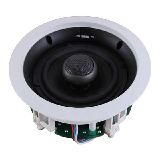
Niles speakers, resulting in positive in-phase connections every time. Moisture, UV Resistant Construction The CM5PR and CM6PR loudspeakers are suitable for use in high moisture environ- ments. The drivers are resistant to moisture and UV exposure; the grille is made of powder-coated aluminum. - Page 4 4 or 8 ohm Selectable Impedance The dual voice coil feature of the CM5PR and CM6PR gives the installer flexibility to select the speaker’s impedance — 4 ohms for systems where maximum current trans- fer and output level is desired;...
-
Page 5: Installation Considerations
“clipping” distortion. A large ampli- 10 to 100 watts for the CM5PR and 10 to fier will play at the same volume without 125 watts for the CM6PR. Curiously, most distorting. - Page 6 Speaker Wire Use 2-conductor speaker wire when con- necting CM5PR and CM6PR speakers to your receiver or amplifier. For most appli- cations, we recommend you use 16 or 18 gauge stranded wire. For wiring runs longer than 80 feet we recommend 14 gauge stranded wire.
-
Page 7: Speaker Placement
You should have a direct line of sight with the front of the speaker. To Introduction Although the CM5PR and CM6PR have determine the best position, measure the “listening” distance between the ideal lis- extensive ability to compensate for unusu-... - Page 8 The speakers must be masked prior to A single pair of CM5PR or CM6PR painting them. The inside circular portion Loudspeakers, properly placed, can create of the hole template can be used as a a very convincing simulation of an array paint mask.
- Page 9 (See Figure 6). With 8. Direct the Tweeter. The tweeter is Niles CM5PR and CM6PR loudspeakers it directed by gently pushing on the edge is easy to add another pair without affect- of the tweeter grille.
-
Page 10: Installation Fundamentals
Then leaving 4-1/8" at one end for the use a chisel to remove all of the plaster CM5PR and 4/3/4" for the CM6PR (this within the taped outline. To actually cut allows for the extra width of the mount- the lathe, two methods are used profes- ing dogs). -
Page 11: Installation In New Construction
Figure 12 The optional hole saving brackets are installed and the speaker wire is attached to the bracket. The wings and brackets have centering Try to line the holes up perfectly, because lines to simplify placement of the speakers. - Page 12 The door jamb has been removed and the speaker wire concealed between the wall and the jamb. Nail plates are installed to protect the wire and the door jamb is replaced Diagram of ceiling speaker cut-out with ceiling joists notched for wire run.