
Related Manuals for Niles AT8


Summary of Contents for Niles AT8
- Page 1 I N S T A L L A T I O N & O P E R A T I O N G U I D E M O D E L S ® L E N D I N G I G H I D E L I T Y ®...
-
Page 2: Table Of Contents
WARRANTY REGISTRATION CARD LIMITED WARRANTY ©2000 Niles Audio Corporation. All rights reserved. Niles, the Niles logo, Blending High Fidelity and Architecture and Systems Integration Amplifiers are registered trademarks of Niles Audio Corporation. BumpBack and MicroSensor are trademarks of Niles Audio Corporation. Dolby is a registered trademark of Dolby Laboratories Licensing Corporation. Decora is a registered trade- mark of Leviton Manufacturing Co. -
Page 3: Limited Warranty
Limited Warranty Niles Audio Corporation ("NILES") warrants its loudspeaker products to the original purchaser to be free of manufacturing defects in material and workmanship for a period of five years from date of purchase. This Warranty is subject to the following additional conditions and limitations. The Warranty... -
Page 4: Warranty Registration Card
WARRANTY REGISTRATION CARD Model Purchased__________________ ____________ _ ____ Serial Number_____________ ____________________ _ __________________________________________________ Date Purchased (month/day/year)_______ _____________________ _ ____ ___________________________ ______ Dealer Name and Location________________ _____ ___________________________________________________ ___________________________________________ _________ ______________________________________________ ❑ Dr. ❑ Miss ❑ Mr. Name______ _________________________________________________ _____________________________________ Address________________________________ _________________________________________________________ ________________________________________________________ ____________________________________ _ _____ City_________________________________________________________State______ __________Zip______________ Telephone (___________)___________________________________________________________________________... -
Page 5: Introduction
They are perfect anywhere that ultimate sound quality is required. An AT5/AT6/AT8 Speaker Kit; and the corresponding Bracket Kit (5, 6 or 8) is required to install one pair of AT5/AT6/AT8 In-Wall loudspeakers in either new or existing construction. - Page 6 No-Strip Speaker Terminal Niles patented No-Strip terminal enables speakers to be connected without strip- ping the speaker wire. No-Strip terminals eliminate fumbling with wire strippers and input terminals. They are color coded and simply plug into the crossover circuit boards on the back of Niles speakers, resulting in positive in-phase connections every time.
- Page 7 PLEASE FILL OUT THE WARRANTY REGISTRATION CARD ON THE REVERSE SIDE, DETACH, AND MAIL TO: Niles Audio Corporation Warranty Registration Dept. P.O. Box 160818 Miami, Florida 33116-0818...
-
Page 9: Installation Considerations
AT5; and ten to one hundred twenty-five watts for the AT6, and ten to one hundred fifty watts for the AT8. Curiously, most speak- ers are not damaged by large amplifiers but by small amplifiers. If your system is playing loudly, a small amplifier will run out of power very quickly. - Page 10 er, so you must connect the wire from the amplifier to the volume control and then from the volume control to the speaker. Speaker Wire Use 2-conductor speaker wire when con- necting AT speakers to your receiver or amplifier. For most applications, we rec- ommend you use 16 or 18 gauge stranded wire.
-
Page 11: Specifications
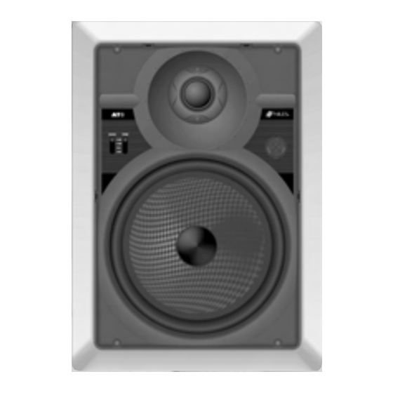
Specifications Model AT8 Driver Compliment 8” Carbon/Glass Fiber Woofer with Dispersion Stabilizer, Custom Debris Screen, High BL Magnet Structure with Vented Pole Piece 1” Teteron Tweeter Housed in a Low Diffraction Precision Adjustment Mechanism Design Principle Infinite baffle for large and varying air... - Page 12 Specifications Model AT5 Driver Compliment 5-1/4” Carbon/Glass Fiber Woofer with Dispersion Stabilizer, Custom Debris Screen, High BL Magnet Structure with Vented Pole Piece 1” Teteron Tweeter Housed in a Low Diffraction Mechanism Design Principle Infinite baffle for large and varying air volumes Recommended Amplifier Power Ten to One Hundred Watts per Channel...
-
Page 13: Speaker Placement
Speaker Placement Placement for Critical Listening If you like to imagine that the band or orchestra is playing in front of you as you listen to music, or you are very conscious of clarity, detail and the textures of the individ- ual instruments, you are a critical listener. - Page 14 The Boundary Effect Corners can affect the bass response of the speaker powerfully! This is called the boundary effect. You will emphasize par- ticular bass frequencies and cancel out other bass frequencies when you place speakers close to the wall/ceiling bound- ary or a corner wall boundary.
- Page 15 Removal of Speaker and Grille Removing The Speaker If the grille is already installed, remove it by using a bent paper clip or the tip of a corkscrew and pulling it away from the frame. Utilizing two small screwdrivers or two needle nose pliers, release the snaps that hold the speaker to the frame.
- Page 16 Adjusting the Tweeter The tweeter is housed in a precision adjust- ment mechanism which enables precise aiming of the directional high frequencies to provide optimum performance. To adjust the tweeter: 1. Carefully grasp the tweeter housing by placing your thumb and forefinger in the indentations provided.
- Page 17 Film makers try to use the “surround” soundtrack to envelope you in the envi- ronment on screen. They will place back- ground music, rain sounds, traffic noise, etc. on the “surround” soundtrack. In a home with a single pair of speakers it is easy for the jungle sounds to sound like they are “in the middle of your head”...
-
Page 18: Installation Fundamentals
Installation Fundamentals Running the Speaker Wire in New Construction If you have doubts about whether you are capable of installing a Niles AT Series speaker in your walls, consult a Niles dealer or professional installer. They have special tools, techniques, and experience to make the impossible possible. - Page 19 Figure 17 Speaker Phase Speaker wire has two conductors. One conductor is attached to the negative (-) terminals and one conductor is attached to the positive (+) terminals of both your speaker and your amplifier. Usually, the wire is marked for your convenience. There are different ways wires are marked: a stripe on one wire, a ribbed area of one conductor you can only feel, different col-...
- Page 20 Installing the Speaker If the grille is already installed, remove it by using a bent paper clip or the tip of a corkscrew and pulling it away from the frame (See Figure 13). 1. Separate the speaker wire so that at least two inches of each conductor are free.
- Page 21 Try to line the holes up perfectly, because it makes pulling the wire much easier. A good technique is to snap a chalk line across the face of the studs or against the bottom of the ceiling joists. Then work backward so that you can always see the holes you have already drilled.
- Page 22 Speaker Location Identify where all of your electrical, phone, and TV wiring is likely to be and plan to route around it all. You can acci- dentally induce 60 Hz hum on your speakers if you run your speaker wire right beside electrical wire for more than a few feet.
- Page 23 the drywall section can be replaced clean- ly if there is an unseen obstruction behind the wall. BE VERY CAREFUL NOT TO SAW THROUGH EXISTING WIRES, PIPES, OR STRUCTURE. IF YOU FEEL ANY EXTRA RESISTANCE AS YOU ARE CUT- TING, STOP. 4.
- Page 24 Installation of Brackets, Frames and Grilles in Existing Walls IMPORTANT: Before you cut into any wall, review the sections on running wire and speaker placement. 1. Drill a 1/8” pilot hole just barely through the wallboard or dry wall (1/2” to 5/8”...
- Page 25 Figure 6 plenum rated wire (check your local building codes, some municipalities require conduit). In traditional wood stud/drywall construc- tion you can cut the hole for the speaker and utilize the large hole to auger holes across, up or down the wall for as far as your drill bit will take you.
-
Page 26: Installation Of Brackets, Frames And Grilles In New Construction
Installation of Brackets, Frames and Grilles in New Construction Stage One: Before Drywall is Hung. Insulating the Wall Cavity. If feasible, fill the wall cavity with insula- tion at this point. Attach the wings to the bracket by snap- ping them into the sides of the bracket. The wings can be shortened by breaking them along the scored lines if their length will interfere with a corner or eaves. - Page 27 the grille with paint. The grille is construct- ed of aluminum with a perfectly even powder coat overall. This powder coat is an ideal primer. Remove the grilles before painting. If you are using spray paint, use two thin coats without any primer.
- Page 28 Niles Audio Corporation 12331 S.W. 130 Street Miami, Florida 33186 Tel: (305) 238-4373 Fax: (305) 238-0185 www.nilesaudio.com © 2000 Niles Audio Corporation. Patents applied for and pending. Printed in Taiwan DS00280ATW...