Table of Contents
Advertisement
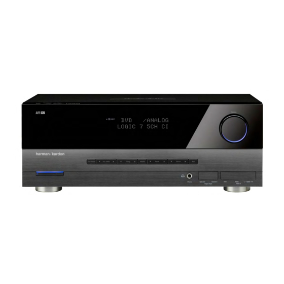
harman/kardon
AVR 139/230
AVR 141/230
AVR 142/230
5 x 40W 5.1 CHANNEL A/V RECEIVER
ESD WARNING
BASIC SPECIFICATIONS
PACKAGE LISTS AND PARTS
Exploded View AND PARTS
Released EU2009
CONTENTS
2
ELECTRICAL PARTS LIST
3
IC LIST
4
SEMICONDUCTOR PINOUTS
4
PCB DRAWINGS
5
BLOCK DIAGRAM
8
WIRING DIAGRAM
9
AMP BIAS ADJUSTMENT
SCHEMATIC DIAGRAMS
Harman Consumer Group, Inc.
8500 Balboa Boulevard
Northridge, California 91329
Service Manual
Rev 0, 04/2009
10
30
31
69
74
75
76
77-83
Advertisement
Table of Contents

Related Manuals for Harman Kardon AVR 139/230


Summary of Contents for Harman Kardon AVR 139/230
-
Page 1: Service Manual
Service Manual AVR 139/230 AVR 141/230 AVR 142/230 5 x 40W 5.1 CHANNEL A/V RECEIVER CONTENTS ESD WARNING ELECTRICAL PARTS LIST BASIC SPECIFICATIONS IC LIST TROUBLESHOOTING GUIDE SEMICONDUCTOR PINOUTS PROCESSOR RESET PCB DRAWINGS PACKAGE LISTS AND PARTS BLOCK DIAGRAM... - Page 2 harman/kardon AVR 139-141-142/230 Service Manual Some semiconductor (solid state) devices can be damaged easily by static electricity. Such components commonly are called Electrostatically Sensitive (ES) Devices. Examples of typical ES devices are integrated circuits and some field effect transistors and semiconductor "chip"...
-
Page 3: Specifications
Height measurement includes feet and chassis. All features and specifications are subject to change without notice. Harman Kardon and logic 7 are trademarks of Harman International Industries, Incorporated, registered in the United states and/or other countries. Designed to Entertain is a trademark of Harman International Industries, Incorporated. -
Page 4: Troubleshooting Guide
Power switch 1 is red due to possible short and speaker ends • Amplifier is in protection mode • Contact your local Harman Kardon service depot due to internal problems No sound from surround or • Incorrect surround mode •... - Page 5 harman/kardon AVR 139-141-142/230 Service Manual Page 5 of 83...
- Page 6 harman/kardon AVR 139-141-142/230 Service Manual Page 6 of 83...
-
Page 7: Manual Ass'y Accessories
harman/kardon AVR 139-141-142/230 Service Manual Page 7 of 83... -
Page 8: Disassembly
harman/kardon AVR 139-141-142/230 Service Manual Page 8 of 83... - Page 9 harman/kardon AVR 139-141-142/230 Service Manual Page 9 of 83...
-
Page 10: Electrical Parts Lists
harman/kardon AVR 139-141-142/230 Service Manual COMPLETE ELECTRICAL PARTS LISTS FOR AVR 139 - AVR 141 - AVR 142 AVR 139 AND AVR 141 ARE IN THE SYSTEMS 13926/13928 AND 14126/14128, WITH DVD 26 AND 28 AVR 142 IS SOLD AS A SEPARATE Parts for AVR 139 only Ref. - Page 11 harman/kardon AVR 139-141-142/230 Service Manual Description Value Ref. # Part Number CQXAVR142/230 INSTRUCTION MANUAL ASS'Y CABR03P3PB BATTERY , AAA 3PCS IN PACK CARTAVR142/230 REMOCON TRANSMITTER ASS'Y CPB1061W BAG , POLY(ENGLISH/FRANCH) FRANCE LANGUAGE ADDED CPL0905 STAPLE CQE1A220Z SHEET , FRONT COVER AVR130/230BK CQE1A411Z SHEET , BATTERY HARMAN...
- Page 12 harman/kardon AVR 139-141-142/230 Service Manual FRONT PCB ASSY Description Value Ref. # Part Number C891 CCBS1H223ZFT CAP , CERAMIC(22000PF/50V) CH UP025 F223Z-A-B J C892 CCBS1H223ZFT CAP , CERAMIC(22000PF/50V) CH UP025 F223Z-A-B J C893 CCBS1H223ZFT CAP , CERAMIC(22000PF/50V) CH UP025 F223Z-A-B J C894 CCEA1CKS100T CAP , ELECT...
- Page 13 harman/kardon AVR 139-141-142/230 Service Manual FRONT PCB ASSY Description Value Ref. # Part Number R904 CRD20TJ102T RES , CARBON 1K OHM 1/5W J R905 CRD20TJ104T RES , CARBON 100K OHM 1/5W J R906 CRD20TJ104T RES , CARBON 100K OHM 1/5W J R907 CRD20TJ472T RES , CARBON...
- Page 14 harman/kardon AVR 139-141-142/230 Service Manual HDMI PCB ASSY Description Value Ref. # Part Number COP12109B HDMI MUX PCB ASS'Y CN45 CJP07GA193ZY WAFER , CARD CABLE SMD C637 CCUS1H104KC CAP , CHIP 0.1UF 50V K C901 CCUS1H104KC CAP , CHIP 0.1UF 50V K C903 CCUS1H104KC CAP , CHIP...
- Page 15 harman/kardon AVR 139-141-142/230 Service Manual MAIN PCB ASSY Description Value Ref. # Part Number C507 CCKT1H331KB CAP , CERAMIC 330PF 50V K C508 CCKT1H331KB CAP , CERAMIC 330PF 50V K C509 CCKT1H331KB CAP , CERAMIC 330PF 50V K C561 CCEA1CH101T CAP , ELECT 100UF 16V C562...
- Page 16 harman/kardon AVR 139-141-142/230 Service Manual MAIN PCB ASSY Description Value Ref. # Part Number C995 HCQI1H473JZT CAP , MYLAR 0.047UF 50V J C997 HCQI1H473JZT CAP , MYLAR 0.047UF 50V J C999 CCFT1H223ZF CAP , CERAMIC 0.022UF 50V Z D501 CVD1SS133MT DIODE 1SS133 D502...
- Page 17 harman/kardon AVR 139-141-142/230 Service Manual MAIN PCB ASSY Description Value Ref. # Part Number Q961 HVTKTA1024YT R501 CRD20TJ433T RES , CARBON 43K OHM 1/5W J R502 CRD20TJ433T RES , CARBON 43K OHM 1/5W J R504 CRD20TJ433T RES , CARBON 43K OHM 1/5W J R505 CRD20TJ433T RES , CARBON...
- Page 18 harman/kardon AVR 139-141-142/230 Service Manual MAIN PCB ASSY Description Value Ref. # Part Number R646 CRD25FJ3R3T RES , CARBON 3.3 OHM 1/4W J R647 CRD25FJ3R3T RES , CARBON 3.3 OHM 1/4W J R648 CRD25FJ3R3T RES , CARBON 3.3 OHM 1/4W J R649 CRD25FJ3R3T RES , CARBON...
- Page 19 harman/kardon AVR 139-141-142/230 Service Manual MAIN PCB ASSY Description Value Ref. # Part Number R897 CRD20TJ391T RES , CARBON R900 CRD20TJ103T RES , CARBON 10K OHM 1/5W J R901 CRD20TJ272T RES , CARBON 2.7K OHM 1/5W J R902 CRD20TJ153T RES , CARBON 15K OHM 1/5W J R903 CRD20TJ153T...
- Page 20 harman/kardon AVR 139-141-142/230 Service Manual MAIN PCB ASSY Description Value Ref. # Part Number CN62 CJP02GA01ZY WAFER , STRAIGHT, 2PIN CN63 CJP02GA01ZY WAFER , STRAIGHT, 2PIN CN64 CJP02GA01ZY WAFER , STRAIGHT, 2PIN CN65 CJP03GA90ZY WAFER CN66 CJP02GA01ZY WAFER , STRAIGHT, 2PIN CN91 CJP02GA89ZY WAFER...
- Page 21 harman/kardon AVR 139-141-142/230 Service Manual INPUT PCB ASSY Description Value Ref. # Part Number C631 CCUS1H104KC CAP , CHIP 0.1UF 50V K C704 CCUS1H104KC CAP , CHIP 0.1UF 50V K C707 CCUS1H102KC CAP , CHIP 1000PF 50V K C719 CCUS1H104KC CAP , CHIP 0.1UF 50V K C738...
- Page 22 harman/kardon AVR 139-141-142/230 Service Manual INPUT PCB ASSY Description Value Ref. # Part Number C312 CCUS1H332KC CAP , CHIP 3300PF 50V K C313 CCUS1H332KC CAP , CHIP 3300PF 50V K C314 CCUS1H332KC CAP , CHIP 3300PF 50V K C317 CCUS1H223KC CAP , CHIP 0.022UF 50V K C318...
- Page 23 harman/kardon AVR 139-141-142/230 Service Manual INPUT PCB ASSY Description Value Ref. # Part Number C798 CCUS1H104KC CAP , CHIP 0.1UF 50V K C801 CCUS1H104KC CAP , CHIP 0.1UF 50V K C803 CCUS1H104KC CAP , CHIP 0.1UF 50V K C805 CCUS1H104KC CAP , CHIP 0.1UF 50V K C806...
- Page 24 harman/kardon AVR 139-141-142/230 Service Manual INPUT PCB ASSY Description Value Ref. # Part Number R204 CRJ10DJ221T RES , CHIP 1608 SIZE R205 CRJ10DJ221T RES , CHIP 1608 SIZE R206 CRJ10DJ221T RES , CHIP 1608 SIZE R209 CRJ10DJ221T RES , CHIP 1608 SIZE R210 CRJ10DJ221T...
- Page 25 harman/kardon AVR 139-141-142/230 Service Manual INPUT PCB ASSY Description Value Ref. # Part Number R332 CRJ10DJ512T RES , CHIP 1608 SIZE R341 CRJ10DJ122T RES , CHIP 1608 SIZE R344 CRJ10DJ122T RES , CHIP 1608 SIZE R345 CRJ10DJ122T RES , CHIP 1608 SIZE R348 CRJ10DJ122T...
- Page 26 harman/kardon AVR 139-141-142/230 Service Manual INPUT PCB ASSY Description Value Ref. # Part Number R761 CRJ10DJ104T RES , CHIP 1608 SIZE R762 CRJ10DJ104T RES , CHIP 1608 SIZE R763 CRJ10DJ472T RES , CHIP 1608 SIZE R764 CRJ10DJ472T RES , CHIP 1608 SIZE R765 CRJ10DJ103T...
- Page 27 harman/kardon AVR 139-141-142/230 Service Manual INPUT PCB ASSY Description Value Ref. # Part Number C606 CCEA1CH101T CAP , ELECT 100UF 16V C608 CCEA1CH101T CAP , ELECT 100UF 16V C610 CCEA1CH101T CAP , ELECT 100UF 16V C612 CCEA1CH101T CAP , ELECT 100UF 16V C614 CCEA1CH101T...
- Page 28 harman/kardon AVR 139-141-142/230 Service Manual VIDEO PCB ASSY Description Value Ref. # Part Number C603 CCBS1H220JCT CAP , CERAMIC(22PF/50V) CH UP025CH220J-A-B Z C604 CCEA0JH102T CAP , ELECT 1000UF 6.3V C605 CCBS1H220JCT CAP , CERAMIC(22PF/50V) CH UP025CH220J-A-B Z C606 CCEA0JH102T CAP , ELECT 1000UF 6.3V C607 CCBS1H220JCT...
- Page 29 harman/kardon AVR 139-141-142/230 Service Manual VIDEO PCB ASSY Description Value Ref. # Part Number COP12189B AVR139/230 GUIDE PCB ASS'Y CN50 CJP06GB142ZB PIN HEADER(6P, 2.54mm) CN51 CJP06GB142ZB PIN HEADER(6P, 2.54mm) CN60 CJP06GB142ZB PIN HEADER(6P, 2.54mm) CN61 CJP06GB142ZB PIN HEADER(6P, 2.54mm) Page 29 of 83...
- Page 30 harman/kardon AVR 139-141-142/230 Service Manual AVR139/230, AVR141/230, AVR142/230 IC List 2009.04.22 PCB Name Ref. # Part No.(Makers) Part No.(ANAM) Description Makers COP12185B (Front PCB Ass'y ) IC73 NJL34H380A HRVNJL34H380A INFRARED REMOTE CONTROL RECEIVER " IC75 74ACT04MTR HVI74ACT04MTR HEX INVERTER " IC76 74HCU04AFNG HVI74HCU04AFNG...
- Page 31 harman/kardon AVR 139-141-142/230 Service Manual Page 31 of 83...
- Page 32 harman/kardon AVR 139-141-142/230 Service Manual Page 32 of 83...
- Page 33 harman/kardon AVR 139-141-142/230 Service Manual Page 33 of 83...
- Page 34 harman/kardon AVR 139-141-142/230 Service Manual Page 34 of 83...
- Page 35 harman/kardon AVR 139-141-142/230 Service Manual 74ACT04 HEX INVERTER HIGH SPEED: t = 5.0ns (TYP.) at V = 5V LOW POWER DISSIPATION: = 2µA(MAX.) at T =25°C COMPATIBLE WITH TTL OUTPUTS = 2V (MIN.), V = 0.8V (MAX.) 50Ω TRANSMISSION LINE DRIVING CAPABILITY TSSOP SYMMETRICAL OUTPUT IMPEDANCE:...
- Page 36 harman/kardon AVR 139-141-142/230 Service Manual Page 36 of 83...
- Page 37 harman/kardon AVR 139-141-142/230 Service Manual Page 37 of 83...
- Page 38 harman/kardon AVR 139-141-142/230 Service Manual SEMICONDUCTOR KIA278R05PI~KIA278R15PI TECHNICAL DATA BIPOLAR LINEAR INTEGRATED CIRCUIT 4 TERMINAL 2A OUTPUT LOW DROP VOLTAGE REGULATOR DIM MILLIMETERS 10.00 0.20 The KIA278R Series are Low Drop Voltage Regulator 15.00 0.20 2.70 0.20 suitable for various electronic equipments. 0.60 0.10 It provides constant voltage power source with TO-220 4 terminal Φ3.20 0.20...
- Page 39 harman/kardon AVR 139-141-142/230 Service Manual Page 39 of 83...
- Page 40 harman/kardon AVR 139-141-142/230 Service Manual KIA1117PI00~ SEMICONDUCTOR KIA1117PI50 TECHNICAL DATA BIPOLAR LINEAR INTEGRATED CIRCUIT LOW DROP FIXED AND ADJUSTABLE POSITIVE VOLTAGE REGULATOR MILLIMETERS The KIA1117PI is a Low Drop Voltage Regulator able 10.30 MAX 15.30 MAX to provide up to 0.8A of output current, available even in adjustable 2.70 0.30 0.85 MAX version (Vref=1.25V)
- Page 41 harman/kardon AVR 139-141-142/230 Service Manual × PIN CONFIGURATION TO-92 • SOT-89 SOT-23-5 • • (mark side) (mark side) (mark side) PIN DESCRIPTION TO-92 SOT-89 SOT-23-5 • • • Pin No. Symbol Pin No. Symbol Pin No. Symbol Page 41 of 83...
- Page 42 harman/kardon AVR 139-141-142/230 Service Manual Page 42 of 83...
- Page 43 harman/kardon AVR 139-141-142/230 Service Manual Page 43 of 83...
- Page 44 harman/kardon AVR 139-141-142/230 Service Manual Page 44 of 83...
- Page 45 harman/kardon AVR 139-141-142/230 Service Manual NJW1197C PIN FUNCTION SYMBOL FUNCTION SYMBOL FUNCTION ROUT Rch output DCR_IN “Multi-channel selector” Rch input COUT Cch output DCR_OUT “Input selector” Rch output LSOUT LSch output Ground RSOUT RSch output DCL_IN “Multi-channel selector” Lch input LBOUT LBch output DCL_OUT...
- Page 46 harman/kardon AVR 139-141-142/230 Service Manual Page 46 of 83...
- Page 47 harman/kardon AVR 139-141-142/230 Service Manual www.fairchildsemi.com KA78LXXA/KA78L05AA 3-Terminal 0.1A Positive Voltage Regulator Features Description • Maximum Output Current of 100mA The KA78LXXA/KA78L05AA series of fixed voltage • Output Voltage of 5V, 6V, 8V, 9V,10V, 12V, 15V, 18V and monolithic integrated circuit voltage regulators are suitable for application that required supply current up to 100mA.
- Page 48 harman/kardon AVR 139-141-142/230 Service Manual www.fairchildsemi.com KA79LXXA 3-Terminal 0.1A Negative Voltage Regulator Features Description • Output Current up to 100mA These regulators employ internal current limiting and • No External Components thermal shutdown, making them essentially indestructible. • Internal Thermal Over Load Protection TO-92 SOT-89 •...
- Page 49 harman/kardon AVR 139-141-142/230 Service Manual Page 49 of 83...
-
Page 50: Top View
harman/kardon AVR 139-141-142/230 Service Manual ASAHI KASEI [AK4589] Ordering Guide -10 ∼ +70°C AK4589VQ 80pin LQFP(0.5mm pitch) AKD4589 Evaluation Board for AK4589 Pin Layout TEST1 INT1 BOUT TVDD DVDD AVSS DVSS AVDD VREFH VCOM TEST3 (Top View) MCKO2 MCKO1 ROUT1+ COUT ROUT1- UOUT... - Page 51 harman/kardon AVR 139-141-142/230 Service Manual LC72723, LC72723M Pin Assignment (DIP16/MFP16) Block Diagram No. 6037-2/8 Page 51 of 83...
- Page 52 harman/kardon AVR 139-141-142/230 Service Manual LC72723, LC72723M Pin Assignment (DIP16/MFP16) Block Diagram No. 6037-2/8 Page 52 of 83...
-
Page 53: Package Pinout 144 Pin
harman/kardon AVR 139-141-142/230 Service Manual Page 53 of 83... - Page 54 harman/kardon AVR 139-141-142/230 Service Manual E S I E S I Excel Semiconductor inc. PIN DESCRIPTION Description A0-A18 19 Addresses DQ0-DQ14 15 Data Inputs/Outputs DQ15 (Data Input/Output, Word Mode) DQ15/A-1 A-1 (LSB Address Input, Byte Mode) Chip Enable Output Enable Write Enable RESET# Hardware Reset Pin, Active Low...
-
Page 55: Connection Diagram
harman/kardon AVR 139-141-142/230 Service Manual E S I E S I Excel Semiconductor inc. CONNECTION DIAGRAM BYTE# DQ15/A-1 48-Pin Standard TSOP DQ14 DQ13 DQ12 RESET# ES29LV800 DQ11 RY/BY# DQ10 48-Ball FBGA (6 x 8 mm) (Top View, Balls Facing Down) DQ15/ BYTE# DQ14... - Page 56 harman/kardon AVR 139-141-142/230 Service Manual HY57V161610E PIN CONFIGURATION DQ15 DQ15 DQ14 DQ14 VSSQ VSSQ DQ13 DQ13 DQ12 DQ12 VDDQ VDDQ DQ11 DQ11 DQ10 DQ10 VSSQ VSSQ VDDQ VDDQ 50pin TSOP II 50pin TSOP II VDDQ VDDQ 400mil x 825mil 400mil x 825mil LDQM LDQM 0.8mm pin pitch...
- Page 57 harman/kardon AVR 139-141-142/230 Service Manual NJM2391 LOW DROPOUT VOLTAGE REGULATOR GENERAL DESCRIPTION PACKAGE OUTLINE The NJM2391 is low dropout voltage regulators featuring high precision voltage. It is suitable for Notebook PCs, PC cards and hard disks where 3.3V need to be generated from 5V supply. NJM2391DL1 A small TO-252 package is adopted for the space saving.
-
Page 58: Data Kia1117S/F00
harman/kardon AVR 139-141-142/230 Service Manual Page 58 of 83... - Page 59 harman/kardon AVR 139-141-142/230 Service Manual × PIN CONFIGURATION TO-92 • SOT-89 SOT-23-5 • • (mark side) (mark side) (mark side) PIN DESCRIPTION TO-92 SOT-89 SOT-23-5 • • • Pin No. Symbol Pin No. Symbol Pin No. Symbol Page 59 of 83...
- Page 60 harman/kardon AVR 139-141-142/230 Service Manual Page 60 of 83...
- Page 61 harman/kardon AVR 139-141-142/230 Service Manual M24C64 M24C32 64Kbit and 32Kbit Serial I²C Bus EEPROM FEATURES SUMMARY Two-Wire I C Serial Interface Figure 1. Packages Supports 400kHz Protocol Single Supply Voltage: – 4.5 to 5.5V for M24Cxx – 2.5 to 5.5V for M24Cxx-W –...
- Page 62 harman/kardon AVR 139-141-142/230 Service Manual M24C64, M24C32 SUMMARY DESCRIPTION These I C-compatible electrically erasable pro- Table 2. Signal Names grammable memory (EEPROM) devices are orga- E0, E1, E2 Chip Enable nized as 8192 x 8 bits (M24C64) and 4096 x 8 bits (M24C32).
- Page 63 harman/kardon AVR 139-141-142/230 Service Manual T5CC1 Pin Assignment and Pin Functions The assignment of input/output pins for the T5CC1, their names and functions are as follows: Pin Assignment Diagram Figure 2.1.1 shows the pin assignment of the T5CC1. 88 P65 DVCC 87 P64/SCOUT 86 P63/INT0...
- Page 64 harman/kardon AVR 139-141-142/230 Service Manual T5CC1 Pin Names and Functions The names of the input/output pins and their functions are described below. Table 2.2.1 Pin names and functions. Table 2.2.1 Pin names and functions (1/3) Number Pin Name Functions of Pins P00 ∼...
- Page 65 harman/kardon AVR 139-141-142/230 Service Manual T5CC1 Table 2.2.1 Pin names and functions (2/3) Number Pin Name Functions of Pins Port 60: I/O port Serial bus interface clock in SIO Mode Port 61: I/O port Output Serial bus interface send data at SIO mode Serial bus interface send/recive data at I C bus mode Open-drain output mode by programmable...
- Page 66 harman/kardon AVR 139-141-142/230 Service Manual 74ACT04 HEX INVERTER HIGH SPEED: t = 5.0ns (TYP.) at V = 5V LOW POWER DISSIPATION: = 2µA(MAX.) at T =25°C COMPATIBLE WITH TTL OUTPUTS = 2V (MIN.), V = 0.8V (MAX.) 50Ω TRANSMISSION LINE DRIVING CAPABILITY TSSOP SYMMETRICAL OUTPUT IMPEDANCE:...
- Page 67 harman/kardon AVR 139-141-142/230 Service Manual NJM2595 5-INPUT 3-OUTPUT VIDEO SWITCH GENERAL DESCRIPTION PACKAGE OUTLINE The NJM2595 is a 5-input 3-output video switch. Its switches select one from five signals received from VTR,TV,DVD, TV-GAME and others. The NJM2595 is designed for audio items, such as AV amplifier and others.
-
Page 68: Data Kia7805Ap/Api
harman/kardon AVR 139-141-142/230 Service Manual Page 68 of 83... - Page 69 harman/kardon AVR 139-141-142/230 Service Manual Page 69 of 83...
- Page 70 harman/kardon AVR 139-141-142/230 Service Manual Page 70 of 83...
- Page 71 harman/kardon AVR 139-141-142/230 Service Manual Page 71 of 83...
- Page 72 harman/kardon AVR 139-141-142/230 Service Manual Page 72 of 83...
- Page 73 AVR 139-141-142/230 Service Manual harman/kardon Page 73 of 83...
- Page 74 harman/kardon AVR 139-141-142/230 Service Manual Page 74 of 83...
- Page 75 AVR139 WIRING.sch-1 - Mon Apr 27 09:56:15 2009 harman/kardon AVR 139-141-142/230 Service Manual Page 75 of 83...
- Page 76 harman/kardon AVR 139-141-142/230 Service Manual AMPLIFIER SECTION BIAS ADJUSTMENT Model : AVR139/230, AVR141/230, AVR142/230 Date 2009.04.28 Rated voltage : AC 230V 50 Hz JM.Kang Measurement condition: No input signal or volume position is minimum. Standard value : 1) Ideal current : 48mA (±...
- Page 77 CUP12185Z_AVR139_FRONT_SHC_MP_090331.sch-1 - Mon Apr 27 10:13:45 2009 harman/kardon AVR 139-141-142/230 Service Manual Page 77 of 83...
- Page 78 harman/kardon AVR 139-141-142/230 Service Manual Page 78 of 83...
- Page 79 harman/kardon AVR 139-141-142/230 Service Manual Page 79 of 83...
- Page 80 harman/kardon AVR 139-141-142/230 Service Manual Page 80 of 83...
- Page 81 harman/kardon AVR 139-141-142/230 Service Manual Page 81 of 83...
- Page 82 harman/kardon AVR 139-141-142/230 Service Manual Page 82 of 83...
- Page 83 CUP12188Z_AVR139_VIDEO_SHC_MP_090331.sch-1 - Mon Apr 27 10:35:18 2009 harman/kardon AVR 139-141-142/230 Service Manual Page 83 of 83...