
Related Manuals for BMW Wallbox Pro


Summary of Contents for BMW Wallbox Pro
- Page 1 BMW i Freude am Fahren Wallbox Pro Installation instructions Installationsanleitung...
- Page 2 61 90 2 288 283 Wallbox ProType 2 (32 A, 7.4 kW) with Power Meter / Wallbox Pro, Typ 2 (32 A, 7,4 kW) mit Stromzähler 61 90 2 288 382 Wallbox ProType 2 (32 A, 7.4 kW) without Power Meter / Wallbox Pro, Typ 2 (32 A, 7,4 kW) ohne Stromzähler...
-
Page 3: Table Of Contents
Contents Safety instruction Aim of this document Features description Scope of delivery Description Installation positions Preparation and mounting Hardware installation Connection Checks before first energizing Safety label Reassembly Commissionning Firmware update Light stripe status Troubleshooting Declaration of Conformity Inhaltsverzeichnis Sicherheitshinweise Über diese Anleitung Funktionsbeschreibung Lieferumfang... -
Page 4: Safety Instruction
CAUTION indicates a potentially hazardous situation which could result in minor or moderate injury. NOTICE NOTICE indicates practices that do not involve the risk of bodily injury. Installation instructions must be retained for future use. Visit our website at: http:// www.bmwgroup.com/360electric/index.html to download the Wallbox Pro Owner's Manual. - Page 5 BMW cannot be held responsible for failure to follow the instructions given in these installation instructions. INFORMATION FOR USE – The Wallbox Pro charging station is designed for a domestic use only. – The Wallbox Pro charging station is designed for charging an electric vehicle indoors or under a shelter.
-
Page 6: Sicherheitshinweise
ACHTUNG weist auf eine mögliche gefährliche Situation hin, die zu leichten oder mittelschweren Verletzungen führen kann. HINWEIS HINWEIS weist auf Verfahren hin, die keine Verletzungsgefahren beinhalten. Die Installationsanleitung sollte für die zukünftige Verwendung aufbewahrt werden. Hier können Sie die Wallbox Pro Bedienungsanleitung herunterladen: http://www.bmwgroup.com/360electric/index.html. - Page 7 BMW kann nicht für die Nichtbefolgung der Anweisungen in dieser Installationsanleitung verantwortlich gemacht werden. INFORMATIONEN ZUR VERWENDUNG – Die Ladestation Wallbox Pro ist nur für eine Verwendung im Haushalt vorgesehen. – Die Ladestation Wallbox Pro wurde zum Aufladen eines Elektrofahrzeugs in Innenräumen oder in geschützten Außenbereichen konzipiert.
-
Page 8: Aim Of This Document
The purpose of this manual is to provide the necessary information for the following operations: – Installation and configuration of BMW Wallbox Pro charging stations. Related documents Owner’s Manual, Quick Start Guide, Installation Guide and information about BMW Service can be downloaded at: http://www.bmwgroup.com/360electric/index.html. DANGER HAZARD OF ELECTRIC SHOCK, EXPLOSION OR ARC FLASH –... -
Page 9: Über Diese Anleitung
Die vorliegende Anleitung soll Ihnen die für die folgenden Vorgänge erforderlichem Information zur Verfügung stellen. – Installation und Konfiguration der Ladestation Wallbox Pro von BMW. Dazugehörige Dokumente Die Bedienungsanleitung, die Kurzanleitung, die Installationsanleitung und die Information über den BMW Service finden Sie unter: http://www.bmwgroup.com/360electric/index.html. -
Page 10: Features Description
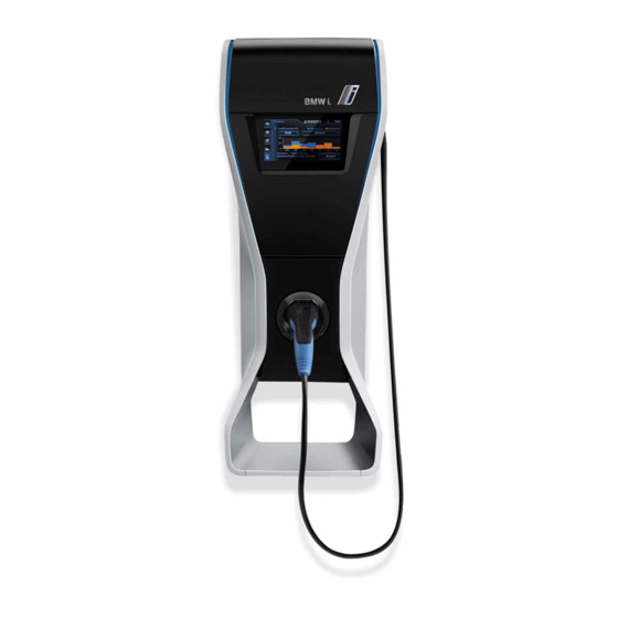
The Wallbox Pro is a 7.4 kW charging station with an attached cable with a Type 2 connector. A power meter (only with Part No. 61 90 2 288 283) is delivered with the Wallbox Pro to enable energy monitoring and energy management. - Page 11 The Wallbox Pro can be connected to a Smart Home System so as to optimize home management holistically: the Smart Home System can start and stop an EV charge as well as allocate power to the Wallbox Pro in accordance with the priorities and customer preferences which were set during configuration.
-
Page 12: Funktionsbeschreibung
Stromzähler Wallbox Pro Die Wallbox Pro ist eine Ladestation mit 7,4 kW Leistung und einem fixierten Kabel mit Type-2- Stecker. Um Energieüberwachung und Energiemanagement zu ermöglichen, wird die Wallbox Pro mit einem Stromzähler geliefert (nur mit Teilenummer 61 90 2 288 283). - Page 13 Fahrzeug vor der geplanten Abfahrtszeit zu laden, kann der Ladevorgang auf das öffentliche Stromnetz umgeschaltet werden, um den Vorgang zu beschleunigen. Die Wallbox Pro kann mit einem Smart Home System verbunden werden, um das Hausmanagement ganzheitlich zu optimieren: Das Smart Home System kann das Laden eines Elektrofahrzeugs starten und stoppen und der Wallbox Pro entsprechend der als Konfiguration vorgegebenen Prioritäten und...
-
Page 14: Scope Of Delivery
1. Scope of delivery / Lieferumfang M5 x 50 M5 x 8 4 x 8 Only with Part no. 61 90 2 288 283 Nur mit Teilenummer 61 90 2 288 283... -
Page 15: Description
2. Description / Beschreibung Light stripes Leuchtstreifen Touch screen Touchscreen Proximity detector Präsenzmelder Vehicle connector Fahrzeugstecker Charging cable Ladekabel RJ45 port RJ45-Anschluss Modbus terminal block Modbus-Klemmleiste Undervoltage remote tripping auxiliary terminal block Klemmleiste für zusätzliche Fernauslösung bei Unterspannung Power supply terminal block Stromversorgungsklemmleiste Network connection cable gland Kabeldurchführung für Netzwerkanbindung... -
Page 16: Installation Positions
NOTICE HAZARD OF EQUIPMENT DAMAGE – Only install the Wallbox Pro outdoors if it is protected from inclement weather conditions. – When performing installation operations which may generate dust, put the Wallbox Pro covers on to protect it and prevent dust from entering. -
Page 17: Preparation And Mounting
4. Preparation and mounting / Vorbereitung und Montage... -
Page 18: Hardware Installation
5. Hardware installation / Hardware-Installation DANGER HAZARD OF ELECTRIC SHOCK, EXPLOSION, OR ARC FLASH – Turn off all power supplying this equipment before working on the equipment. – Always use an appropriate voltage detection device to confirm the absence of voltage. –... - Page 19 Power cables / Stromversorgungskabel Optional cables / Optionale Kabel The fixing screws must be supplied by the installer and selected according to the Wallbox Pro weight and the wall type. Die Befestigungsschrauben sind von dem Installateur bereitzustellen und je nach Gewicht der Wallbox...
-
Page 22: Connection
HAZARD OF ELECTRIC SHOCK, EXPLOSION OR ARC FLASH – Verify that the Wallbox Pro is protected with a circuit breaker and a 30 mA type A residual current device, installed in the switchboard. Systems that automatically reset the Residual Current Device are prohibited (standard IEC 61651-22). -
Page 23: Verbindung
Bestimmungen für elektrische Anlagen entsprechen. – Nehmen Sie die Wallbox Pro nicht in Betrieb, wenn der gemessene Erdwiderstand nicht den geltenden Bestimmungen für elektrische Anlagen entspricht. Verwenden Sie die Wallbox Pro in diesen Fällen nicht. - Page 24 Connection / Verbindung Position of metering points according to domestic energy connection Die Zählpunkte werden gemäß der Anbindung des selbst erzeugtem Stroms (Eigenstroms) angeordnet Installation Case 1 Installation Case 2 Installation Case 3 Installationsszenarium 1 Installationsszenarium 2 Installationsszenarium 3 Utility meter / Stromzähler des Energieversorgers House / Haus Electric vehicle / Elektrofahrzeug Domestic energy / Selbst erzeugter Strom (Eigenstrom)
- Page 25 (3) Installation case 2 specifically: power allocated to electric vehicle charging during power reduction phases will not take into consideration the additionnal on-site domestic energy power generation. (4) For a 3 phase feed house, the maximum power available for the Wallbox Pro is 1/3 of the total installed power in the house.
- Page 26 Single phase feed / Einphasige Einspeisung (I1) (I2) (I3) ∼220/240V U< Wallbox Pro – Q1: main circuit breaker – Q2: circuit breaker: rating 40 A (recommended) - C curve, Residual Current Device: rating 30 mA - A type (A Si type recommended) –...
- Page 27 Three phase feed / Dreiphasige Einspeisung (I1) (I2) (I3) ∼380/415V∼ U< Wallbox Pro – Q1: main circuit breaker – Q2: circuit breaker: rating 40 A (recommended) - C curve Residual Current Device: rating 30 mA - A type (A Si type recommended) –...
- Page 28 Bi phase feed / Zweiphasige Einspeisung (I1) (I2) (I3) ∼220/240V∼ U< Wallbox Pro – Q1: main circuit breaker – Q2: circuit breaker: rating 40 A (recommended) - C curve Residual Current Device: rating 30 mA - A type (A Si type recommended) –...
- Page 29 Network connection (Smart Home System or internet) Netzwerkanbindung (Smart Home System oder Internet) Modbus RS485 (Power Meter) / Modbus RS485 (Stromzähler) Undervoltage remote tripping auxiliary (optional) / Zusätzliche Fernauslösung bei Unterspannung (optional) 230 V∼ WARNING FIRE HAZARD Wire the power supply cable to its terminals only as indicated in the drawings of this document. Failure to follow these instructions can result in death, serious injury or equipment damage.
- Page 30 6.2 Wallbox Pro power supply connection / Stromversorgungsanschluss der Wallbox Pro Note: connect the the power supply cable at the end for easier wiring. Hinweis: Verbinden Sie das Stromversorgungskabel am Ende, um die Verdrahtung zu vereinfachen.
- Page 31 6.3 Wallbox Pro connection to power meter (Modbus RS485) only with Part No 61 90 2 288 283 / Verbindung der Wallbox Pro mit dem Stromzähler (Modbus RS486) nur mit Teilenummer 61 90 2 288 283 Modbus: Shielded twisted pair, (STP)
- Page 32 6.4 Power meter configuration / Stromzählerkonfiguration Refer to the documentation of the power meter / Sehen Sie die Dokumentation des Stromzählers...
- Page 33 6.5 Connection of undervoltage remote tripping auxiliary (optional) Anschluss der zusätzlichen Fernauslösung bei Unterspannung (optional)
- Page 34 6.6 Wallbox Pro connection to IT network (RJ45) optional Anbindung der Wallbox Pro an das IT-Netzwerk (RJ45) optional Ethernet: Cat 5 Ethernet cable, FTP or STP / Ethernet: Cat-5-Ethernet-Kabel, FTP oder STP...
-
Page 35: Checks Before First Energizing
– Überprüfen Sie die Anbindungen der Stromkabel. Entfernen Sie Schmutz und Schutt, der während – Überprüfen Sie die Anbindungen der der Installation möglicherweise in die Wallbox Pro Anschlusskabel. gelangt ist. – Überprüfen Sie, dass alle Kabeldurchführungen festgezogen sind. Bei Nichtbeachtung dieser Anweisungen kommt es zu ernsthaften oder sogar –... -
Page 36: Safety Label
8. Safety label / Sicherheitsetikett Remove the safety label and the warning label in the corresponding language from the supplied sheet and stick them to the 2 marked locations Sicherheitsetikett und Warnhinweis in der entsprechenden Sprache vom mitgelieferten Blatt abziehen und an den 2 markierten Stellen anbringen. -
Page 37: Reassembly
9. Reassembly / Neumontage... -
Page 38: Commissionning
10. Commissionning / Inbetriebnahme 10.1 First energizing / Erstes Einschalten System Initialising Select language Sprache auswählen User Data Login User Name J. SMITH User Data User Name: PIN Code Query Accept Create User Press the « user name » entry field Create user* Eingabefeld «... - Page 39 3.4 kW 4.0 kW Mains Current Domestic Energy Overview window Übersichtsfenster Domestic energy Selbst erzeugter Strom (Eigenstrom) Smart home Smart Home Load management Lademanagement Wallbox Pro settings Einstellungen der Wallbox Pro Screen name Bildschirmname User name Benutzername Icon Symbol Time Uhrzeit...
- Page 40 10.3.Wallbox Pro configuration / Konfiguration der Wallbox Pro Overview 14:07 Wallbox 14:07 J.SMITH J. SMITH 21ºC Smart Last Display Settings Home Management Date and Time User Accounts 3,4 kW Charging History 4,0 kW Error Log Mains Current Domestic energy Installation Press the Wallbox Pro settings button Press on “Installation”...
- Page 41 10.3.1 Domestic energy (optional, only with part. no. 61 90 2 288 283) / Selbst erzeugter Strom (Eigenstrom) (optional, nur mit Teilenummer 61 90 2 288 283) Installation Menu - Domestic Power Installation Menu - Domestic Power Domestic Power Source Connected Domestic Power Source Connected Select Type of Power Source Select Type of Power Source...
- Page 42 Press the Accept button – The function activation can be checked If load management is performed by the on the Wallbox Pro overview window: Smart Home System, refer to the Smart the load management icon should be Home System intallation guide.
- Page 43 Default values are generally compliant with network settings – IP address: Wallbox Pro has a fixed IP address; the default value should be changed only if a different fixed IP address is needed: Note: the IP address immediately following this IP address is also reserved for internal use in the Wallbox Pro –...
- Page 44 Windows 7 / Vista – Click on the "start menu" icon (left botton corner)/ press the windows key on the keyboard – In the search field, write cmd – Press return key – A window with a black background should be open. In this window, type ipconfig –...
- Page 45 Die Standardwerte stimmen im Allgemeinen mit den Netzwerkeinstellungen überein – IP-Adresse: Die Wallbox Pro verfügt über eine feste IP-Adresse. Die Standardwerte sollten nur dann geändert werden, wenn eine andere feste IP-Adresse erforderlich ist. Hinweis: Die IP-Adresse, die gleich nach dieser IP-Adresse kommt, ist ebenfalls für den internen Gebrauch innerhalb der Wallbox Pro reserviert –...
- Page 46 Windows 7 / Vista – Klicken Sie links unten auf das Symbol „Startmenü“ / drücken Sie die Windows-Taste auf der Tastatur – Geben Sie cmd in das Suchfeld ein – Drücken Sie die Eingabetaste – Es sollte sich ein Fenster mit schwarzem Hintergrund öffnen. Geben Sie in diesem Fenster ipconfig ein –...
- Page 47 Pro. Accept The Wallbox Pro is designed for a rated currentadjustable up to 32 A (rated power up to 7.4 kW, 220-240 V) but has a factory-set rated current of 10 A. The factory setting can be modified in increments of 1 amp (from 8 to 32 A) to increase or decrease the Wallbox Pro rated current according to the electrical installation current supply characteristics.
- Page 48 Back With Power meter: select the « Power meter connected » Without Power meter: put the value of the input voltage of the Wallbox Pro (from 220 to 240 V) Mit Stromzähler: « Stromzähler angeschlossen » auswählen Ohne Stromzähler: Wert der...
- Page 49 HAZARD OF OVERHEATING OR FIRE – Do not reset the settings unless you know how to configure the Wallbox Pro. All parameters will be erased and replaced by factory settings, including any derating that limits the current on the electrical installation.
- Page 50 10.4 User settings / Benutzereinstellungen Press the symbol to access the Selection menu. Wallbox Drücken Sie das Symbol, um auf das Auswahlmenü zuzugreifen. Display Settings Date and Time User Accounts Charging History Error Log Installation For more information about user’s settings, refer the owner’s manual Weitere Informationen zu den Benutzereinstellungen finden Sie in der Bedienungsanleitung http://www.bmwgroup.com/360electric/index.html...
- Page 51 – Choose a USB flash drive according to firmware file sizes – Choose a USB flash drive that can be plugged into the Wallbox Pro (length: 90 mm, width: 25 mm) – Do not change firmware files or directory names –...
-
Page 52: Firmware Update
11. Navigate to the update screen 12. Update the Wallbox Pro controller software 13. Navigate to the update screen and check to ensure that the user interface and Wallbox Pro controller software versions are the desired ones 14. Switch off the Wallbox Pro power supply (Q2) 15. - Page 53 Öffnen Sie die Wallbox Pro gemäß der Beschreibung in der vorliegenden Anleitung Stecken Sie den USB-Stick ein Schrauben Sie die Abdeckung an, um das Elektrofach der Wallbox Pro zu schließen Schalten Sie die Stromversorgung der Wallbox Pro ein (Q2) Drücken Sie „YES“ (1) um die Benutzeroberfläche zu aktualisieren Warten Sie den automatischen Neustart ab und drücken Sie anschließend „RESTART“...
-
Page 54: Light Stripe Status
Status Vehicle is not connected. Wallbox Pro is ready for charging. Vehicle is connected. Vehicle timer is activated. Wallbox Pro is waiting for the charging to start. Solid blue light Vehicle is connected. Charging process paused by user. Vehicle is connected. - Page 55 12. Zustände der Leuchtstreifen Leuchtstreifen Zustand Fahrzeug ist nicht angeschlossen. Wallbox Pro ist ladebereit. Fahrzeug ist angeschlossen. Fahrzeug-Timer ist aktiviert. Wallbox Pro wartet auf den Beginn des Blaues Ladevorgangs. Dauerlicht Fahrzeug ist angeschlossen. Ladevorgang durch Benutzer angehalten. Fahrzeug ist angeschlossen.
-
Page 56: Troubleshooting
13. Troubleshooting / Fehlerbehebung DANGER HAZARD OF ELECTRIC SHOCK, EXPLOSION, OR ARC FLASH – Turn off all power supplying this equipment before working on the equipment. – Always use an appropriate voltage detection device to confirm the absence of voltage. Failure to follow these instructions will result in death or serious injury. - Page 57 Behaviour Actions No display on the 1. Check to ensure that the upstream charging station circuit breakers are not in screen the tripped position 2. Check the power supply connection 3. If the problem persists, contact Customer Service Screen does not 1.
- Page 58 Behaviour Actions The light stripes See detailed information in the event reporting section are flashing red...
- Page 59 Verhalten Maßnahme Keine Anzeige auf 1. Überprüfen Sie, dass die Leistungsschutzschalter vor der Ladestation nicht in dem Bildschirm ausgelöster Position sind 2. Überprüfen Sie den Stromversorgungsanschluss 3. Sollte das Problem fortbestehen, den Kundendienst benachrichtigen Bildschirm 1. Überprüfen Sie die Betriebszeit auf dem Bildschirm schaltet sich nicht 2.
- Page 60 Verhalten Maßnahme Unerwünschtes Wenn die Leuchtstreifen rot blinken, sehen Sie die detaillierten Informationen im Stoppen des Abschnitt Ereignis-Berichterstattung. Wenn die Leuchtstreifen nicht rot blinken: Ladevorgangs 1. Trennen Sie den Stecker des Ladekabels vom Fahrzeug 2. Überprüfen Sie, dass die Ladestation ladebereit ist (Farbe der Leuchtstreifen und Anzeige auf dem Bildschirm) 3.
- Page 61 13.1 Events reporting / Ereignis-Berichterstattung Flashing red / Rotes Blinklicht Wallbox Error Log Date/ Note Code time...
- Page 62 Check if the cable is correctly plugged. Red blinking Wallbox Pro and the vehicle. Test the Wallbox Pro with an appropriate testing device to differentiate if the The charge has been stopped. issue origin is within the car or the Wallbox Pro.
- Page 63 Check Ethernet connection on both side. No blinking Smart Home System. The charge will Check Smart Home System configuration. Check IP address and network continue with the Wallbox Pro own settings. mask. (*) One user, one profile and no PIN = no blinking...
- Page 64 Überprüfen Sie, dass das Kabel korrekt angeschlossen ist. Rotes ist ein Kommunikationsproblem aufgetreten. Testen Sie die Wallbox Pro mit einem geeigneten Testgerät, um zwischen dem Blinklicht Der Ladevorgang wurde gestoppt. Fahrzeug und der Wallbox Pro als Ursprung des Problems unterscheiden zu können.
- Page 65 Überprüfen Sie die Ethernet-Verbindung auf beiden Seiten. Blinkt nicht System kommunizieren. Der Ladevorgang Überprüfen Sie die Konfiguration des Smart Home Systems. wird mit den Einstellungen der Wallbox Pro Überprüfen Sie die IP-Adresse und Netzwerkmaske. fortgesetzt. (*) Ein Benutzer, ein Profil und keine PIN = Blinkt nicht...
- Page 66 13.2 Internal connection positions / Interne Anschlusspositionen Proximity sensor connection / Proximity sensor connection Light stripes connection / Anbindung der Leuchtstreifen RJ45 port / RJ45-Stecker...
- Page 67 Declaration of Conformity / Konformitätserklärung The complete CE Declaration of Conformity (Low Voltage Directive LVD and Electromagnetic Compatibility Directive EMC) can be found on the following website of the manufacturer: Die vollständige CE-Konformitätserklärung (Niederspannungsrichtlinie und EMV-Richtlinie) ist auf der folgenden Website des Herstellers zu finden:...
- Page 68 Mehr über BMW www.bmw.de www.bmw.com Freude am Fahren EAV7262601-01 07/2014...