U-Line 2224BEV User Manual
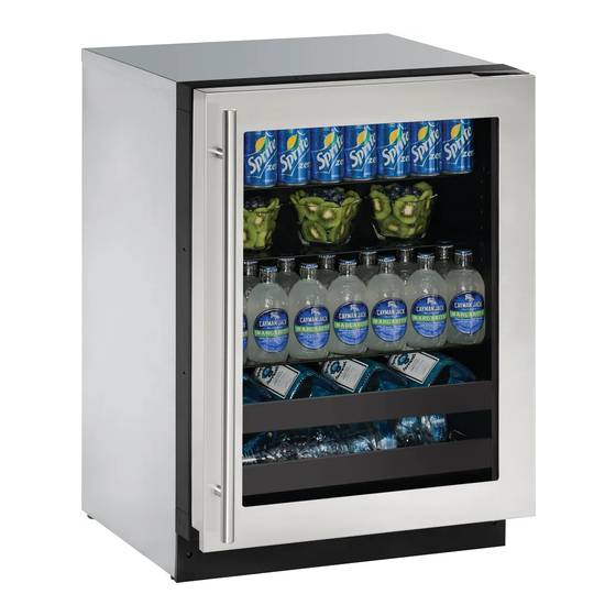
24" beverage center
Hide thumbs
Also See for 2224BEV:
- User manual & service manual (68 pages) ,
- User manual (39 pages) ,
- User manual & service manual (58 pages)

Related Manuals for U-Line 2224BEV


Summary of Contents for U-Line 2224BEV
- Page 1 USER GUIDE SAFETY • INSTALLATION & INTEGRATION • OPERATING INSTRUCTIONS • MAINTENANCE • SERVICE RIGHT PRODUCT. RIGHT PLACE. RIGHT TEMPERATURE. SINCE 1962. 2000 Series 2224BEV 24" Beverage Center • •...
-
Page 2: Table Of Contents
USER GUIDE u-line.com SAFETY • INSTALLATION & INTEGRATION • OPERATING INSTRUCTIONS • MAINTENANCE • SERVICE Contents Intro Installation Integrated Panel Dimensions Integrated Grille / Plinth Dimensions Integrated Panel Installation Grille / Plinth Installation... -
Page 3: U-Line.com
1. U-Line Customer Care must be contacted immediately at +1.800.779.2547. 2. Service or repairs performed on the unit without prior written approval from U-Line is not permitted. If the unit has been altered or repaired in the field without prior written approval from U-Line, claims will not be eligible. -
Page 4: Integrated Panel Dimensions
USER GUIDE u-line.com SAFETY • • OPERATING INSTRUCTIONS • MAINTENANCE • SERVICE INSTALLATION & INTEGRATION Integrated Panel Dimensions Integrated Panel Dimensions INTEGRATED PANEL 3/4" BACK SURFACE MUST HAVE AMPLE FLAT SURFACE (20 mm) TO MOUNT OVERLAY PANEL FLAT AND WITHOUT... - Page 5 23-3/8" (594 mm) 3-1/2" (89 mm) solution for a handleless, integrated design that can be easily applied to your U-Line 3000 Series model. Consult your cabinet manufacturer for applicable design and installation details. The cabinet manufacturer’s solution to Wooden Insert...
- Page 6 USER GUIDE u-line.com SAFETY • • OPERATING INSTRUCTIONS • MAINTENANCE • SERVICE INSTALLATION & INTEGRATION Handleless Integrated Panel Dimensions 1/8" (3 mm) Top Design 1/4" (6 mm) 7/8" (22 mm) Ref. 2-3/8" R 5/8" (60 mm) (R16 mm) 23-3/8" (594 mm) 2-3/4"...
- Page 7 USER GUIDE u-line.com SAFETY • • OPERATING INSTRUCTIONS • MAINTENANCE • SERVICE INSTALLATION & INTEGRATION EXTENDED INTEGRATED PANEL NOTICE Due to differences in surrounding cabinetry the panel may not perfectly align with door. The procedure below is designed to provide a finished panel that seamlessly integrates with surrounding cabinetry.
- Page 8 USER GUIDE u-line.com SAFETY • • OPERATING INSTRUCTIONS • MAINTENANCE • SERVICE INSTALLATION & INTEGRATION Integrated Panel/Integrated Frame Integrated Panel U-Line U-Line Cabinet Unit Unit 3-5/16" (89 mm) 3-5/16" (89 mm) > 3-5/16" (> 89 mm) 4-5/16" (114 mm) 4-5/16" (114 mm)
- Page 9 USER GUIDE u-line.com SAFETY • • OPERATING INSTRUCTIONS • MAINTENANCE • SERVICE INSTALLATION & INTEGRATION Extended Integrated Panel Dimensions 3/4" BACK SURFACE MUST HAVE AMPLE FLAT SURFACE (20 mm) TO MOUNT OVERLAY PANEL FLAT AND WITHOUT INTERFERENCE 23-3/8" (594 mm) 32-7/8"...
-
Page 10: Integrated Grille / Plinth Dimensions
3. Apply double sided tape to the backside of the integrated grill (plinth strip/base fascia). Use the diagram below for reference. U-Line recommends ™ ™ tape, a high strength bonding tape. -
Page 11: Integrated Panel Installation
6. Secure integrated panel to door using Clamp 1. Fully open door. clamps. A robust tape may also be used. U-Line 2. Starting at corner, pull recommends the gasket away from door. use of bar clamps Door/Drawer to secure the panel 3. - Page 12 USER GUIDE u-line.com SAFETY • INSTALLATION & INTEGRATION • OPERATING INSTRUCTIONS • MAINTENANCE • SERVICE 10.Be sure the screws force their way past the opening on the gasket channel and sit flush against the bottom of the channel. Integrated Panel Integrated Panel 11.Remove clamps from door.
-
Page 13: Grille / Plinth Installation
USER GUIDE u-line.com SAFETY • INSTALLATION & INTEGRATION • OPERATING INSTRUCTIONS • MAINTENANCE • SERVICE Grille - Plinth Installation REMOVING AND INSTALLING GRILLE (PLINTH STRIP/BASE FASCIA) WARNING Disconnect electric power to the unit before removing the grille (plinth strip/base fascia).