Sign In
Upload
Manuals
Brands
Bosch Manuals
Tyre Changers
Start Line TCE 420
Bosch Start Line TCE 420 Manuals
Manuals and User Guides for Bosch Start Line TCE 420. We have
2
Bosch Start Line TCE 420 manuals available for free PDF download: Original Instructions Manual, Repair Instructions
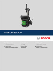
Bosch Start Line TCE 420 Original Instructions Manual (144 pages)
Brand:
Bosch
| Category:
Tyre Changers
| Size: 3.67 MB
Table of Contents
Deutsch
4
Table of Contents
4
1 Verwendete Symbolik
5
In der Dokumentation
5
Warnhinweise - Aufbau und Bedeutung
5
Symbole - Benennung und Bedeutung
5
Auf dem Produkt
5
Warnung
5
2 Benutzerhinweise
6
Allgemeine Bestimmungen
6
Einsatzbereich
6
Anforderungen und Hinweise zur Betriebssicherheit
7
3 Produktbeschreibung
8
Bestimmungsgemäße Verwendung
8
Typenschild
8
Gerätebeschreibung
8
Lieferumfang
9
4 Transport
9
Transport und Verpackung
9
Transportmethode
9
5 Auspacken
9
TCE 420 Aufstellen
9
6 Erstinbetriebnahme
11
TCE 420 Befestigen
12
TCE 420 an Strom- und Druckluftversorgung Anschließen
12
Pedalfunktionen Prüfen
12
7 Bedienung
13
Sicherheitshinweis
13
Vor dem Betrieb Prüfen
13
Hinweise zu Besonderen Felgen und Reifen
13
Abdrücken der Reifenwulst
14
Ausrichtung der Felge
15
Einspannen der Felge
16
Spannen der Felge von Außen
16
Spannen der Felge von Innen
16
Reifen Demontieren
16
Montagekopf Positionieren
17
Oberen Wulst über das Felgenhorn Hebeln
17
Oberen Wulst Demontieren
18
Unteren Wulst Demontieren (mit Montagekopf)
18
Räder Abnehmen
18
Reifen Montieren
18
Auswahl des Reifens
19
Reifen Vorbereiten
19
Montagekopf Positionieren
19
Unteren Wulst Montieren
19
Oberen Wulst Montieren
19
Ablauf der Montage/Demontage bei
20
Leichtmetallfelgen
20
8 Befüllen
20
Befüllung von Schlauchlosreifen
21
Befüllung von Reifen mit Schläuchen
21
9 Wartung
22
Warnung
22
Wartungsschritte
22
Wartungseinheit und Wulstabdrückzylinder
22
Riemen
23
10 Hinweise bei Störungen
24
11 Außerbetriebnahme
25
Ortswechsel
25
Vorübergehende Stilllegung
25
Entsorgung und Verschrottung
25
Wassergefährdende Stoffe
25
TCE 420 und Zubehör
25
12 Technische Parameter
26
Abmessungen
26
Einsatzbereich
26
Drehtellertyp
26
Abdrückschaufel
26
Leistung
26
Pneumatik-Schaltbild
26
English
27
1 Symbols Used
28
In the Documentation
28
Warning Notices - Structure and Meaning
28
Symbols in this Documentation
28
On the Product
28
Warning
28
2 User Instructions
29
General Provision
29
Range of Application
29
Safety Requirements and Notes
30
3 Product Description
31
Intended Use
31
Machine Rating Plate
31
Device Description
31
4 Transport
32
Transport and Packing
32
Transport Method
32
5 Unpacking
32
Setting up the TCE
32
Scope of Delivery
32
6 Initial Commissioning
34
Fastening the TCE
35
Connecting the TCE 420 to Power and the Compressed Air Supply
35
Checking the Pedal Functions
35
7 Operation
36
Safety Notice
36
Check before Use
36
Information about Special Rims and Tires
36
Unseating the Tire Bead
37
Rim Location Direction
38
Clamping the Rim
39
Clapping the Rim from the Outside
39
Clamping the Rim from the Inside
39
Demounting the Tire
39
Positioning of the Mounting Head
40
Lever the Top Bead over the Rim Flange
40
Demounting the Top Bead
41
Demounting the Bottom Bead (with the Aid of the Mounting Head)
41
Removing Wheels
41
Mounting the Tire
41
Selecting the Tire
42
Preparing the Tire
42
Positioning of the Mounting Head
42
Mounting the Lower Tire Bead
42
Mounting the Top Bead
42
Procedure for Mounting/Demounting Alloy Rims
43
8 Inflation
43
Inflating Tubeless Tires
44
Inflating Tubed Tires
44
9 Maintenance
45
Warning
45
Maintenance Operations
45
Maintenance Unit and Bead Breaking Cylinder
45
Belt
46
10 Troubleshooting
47
11 Decommissioning
48
Change of Location
48
Temporary Shutdown
48
Disposal and Scrapping
48
Substances Hazardous to Water
48
TCE 420 and Accessories
48
12 Technical Parameter
49
Dimensions for
49
Range of Application
49
Turntable Type
49
Bead Breaker Blade
49
Power
49
Pneumatic Diagram
49
Français
50
1 Symboles Utilisés
51
Dans la Documentation
51
Avertissements - Conception
51
Et Signification XXX
51
Symboles - Désignation Et Signification
51
Sur Le Produit
51
Avertissement
51
2 Consignes Utilisateur
52
Dispositions Générales
52
Domaine D'application
52
Exigences Et Remarques Relatives À la Sécurité D'exploitation
53
3 Description du Produit
54
Utilisation Conforme
54
Plaque Signalétique
54
Description de L'appareil
54
Contenu de la Livraison
55
4 Transport
55
Transport Et Emballage
55
Méthode de Transport
55
5 Déballage
55
Installation du TCE
55
6 Première Mise en Service
57
Fixer Le TCE
58
Raccordement du TCE 420 Au Courant Électrique Et À L'alimentation en Air Comprimé
58
Contrôle des Fonctions de Pédales
58
7 Utilisation
59
Consigne de Sécurité
59
Contrôler Avant Utilisation
59
Remarques Relatives À des Jantes Et Pneumatiques Particuliers
59
Détalonnage du Talon de Pneumatique
60
Ajustage de la Jante
61
Serrage de la Jante
62
Serrage de la Jante de L'extérieur
62
Serrage de la Jante de L'intérieur
62
Démonter Les Pneumatiques
62
Positionnement de la Tête de Montage
63
Faire Levier Pour Passer Le Talon Supérieur Au-Dessus du Bord de la Jante
63
Démontage du Talon Supérieur
64
Démontage du Talon Inférieur (Avec la Tête de Montage)
64
Retrait des Roues
64
Montage des Pneumatiques
64
Sélection du Pneumatique
65
Préparation du Pneumatique
65
Montage du Talon de Pneumatique Inférieur
65
Montage du Talon de Pneumatique Supérieur
65
Déroulement du Montage/Démontage Pour des Jantes en Alliage Léger
66
8 Gonflage
66
Gonflage de Pneumatiques Sans Chambre À Air
67
Gonflage de Pneumatiques Avec Chambres À Air
67
9 Entretien
68
Avertissement
68
Etapes de Maintenance
68
Conditionneur Et Vérin Pousseur
68
Courroies
69
10 Remarques en Cas de Dysfonctionnements
70
11 Mise Hors Service
71
Déplacement
71
Mise Hors Service Provisoire
71
Elimination Et Mise Au Rebut
71
Substances Dangereuses Pour Les Eaux
71
TCE 420 Et Accessoires
71
12 Paramètres Techniques
72
Dimensions
72
Domaine D'application
72
Type de Plateau de Rotation
72
Pale de Compression
72
Puissance
72
Schéma des Connexions Pneumatiques
72
Español
73
1 Símbolos Empleados
74
En la Documentación
74
Advertencias: Estructura y Significado
74
Símbolos en Esta Documentación
74
En el Producto
74
Advertencia
74
2 Indicaciones para el Usuario
75
Disposiciones Generales
75
Ámbito de Utilización
75
Requisitos E Indicaciones para la Seguridad de Funcionamiento
76
3 Descripción del Producto
77
Uso Conforme a lo Previsto
77
Placa de Características
77
Volumen de Suministro
78
4 Transporte
78
Transporte y Embalaje
78
Método de Transporte
78
5 Desembalar
78
Instalar el Producto TCE
78
6 Primera Puesta en Servicio
80
Fijar el TCE
81
Conectar TCE 420 al Suministro de Corriente y Aire Comprimido
81
Comprobación del Funcionamiento del Pedal
81
7 Manejo
82
Indicación de Seguridad
82
Comprobar Antes de la Puesta en Servicio
82
Nota sobre Llantas y Neumáticos Especiales
82
Separación del Talón del Neumático
83
Alineación de la Llanta
84
Bloqueo de la Llanta
85
Montaje de la Llanta desde Fuera
85
Montaje de la Llanta desde dentro
85
Desmontar el Neumático
85
Posicionar el Cabezal de Montaje
86
Apalancar el Talón Superior por Encima de la Pestaña de la Llanta
86
Desmontaje del Talón Superior
87
Desmontaje del Talón Inferior (con Cabezal de Montaje)
87
Retirar las Ruedas
87
Montar el Neumático
87
Selección del Neumático
88
Preparación del Neumático
88
Posicionar el Cabezal de Montaje
88
Montar el Talón Inferior
88
Montar el Talón Superior del Neumático
88
Proceso de Montaje / Desmontaje en Llantas de Aleación
89
8 Llenado
89
Llenado de Neumáticos sin Cámara
90
Llenar Los Neumáticos con Tuberías Flexible de Servicio
90
9 Mantenimiento
91
Advertencia
91
Pasos de Mantenimiento
91
Unidad de Mantenimiento y Cilindro Destalonador
91
Correa
92
10 Instrucciones en Caso de Averías
93
11 Puesta Fuera de Servicio
94
Cambio de Lugar
94
Puesta Fuera de Servicio Temporal
94
Eliminación y Desguace
94
Materiales Peligrosos para el Agua
94
TCE 420 y Accesorios
94
12 Parámetros Técnicos
95
Dimensiones
95
Ámbito de Utilización
95
Tipo de Base Giratoria
95
Paleta Destalonadora
95
Potencia
95
Diagrama de Conexiones Neumáticas
95
Italiano
96
1 Simboli Utilizzati
97
Nella Documentazione
97
Indicazioni DI Avvertimento - Struttura E
97
Significato
97
Simboli Nella Presente
97
Documentazione XXX
97
Sul Prodotto
97
Avvertenze
97
2 Istruzioni Per L'utente
98
Norme Generali
98
Campo D'impiego
98
Requisiti E Istruzioni Per la Sicurezza DI Funzionamento
99
3 Descrizione del Prodotto
100
Impiego Previsto
100
Targhetta DI Identificazione
100
Descrizione del Dispositivo
100
Fornitura
101
4 Trasporto
101
Trasporto E Imballaggio
101
Sistema DI Trasporto
101
5 Disimballaggio
101
Installare Il Prodotto TCE
101
6 Prima Messa in Esercizio
103
Fissaggio DI TCE
104
Collegare TCE 420 All'alimentazione Elettrica E DI Aria Compressa
104
Verificare Le Funzioni del Pedale
104
7 Uso
105
Avviso Sulla Sicurezza
105
Verificare Prima Dell'uso
105
Indicazioni Per Cerchi E Ruote Speciali
105
Estrazione del Tallone Dello Pneumatico
106
Orientamento del Cerchio
107
Montaggio del Cerchio
108
Bloccaggio Dello Pneumatico Dall'esterno
108
Bloccaggio Dello Pneumatico Dall'interno
108
Smontaggio Dello Pneumatico
108
Posizionare L'utensile DI Montaggio
109
Sollevare Il Tallone Superiore Oltre Il Bordo del Cerchio
109
Smontaggio del Tallone Superiore
110
Smontaggio del Tallone Inferiore (con Utensile DI Montaggio)
110
Smontare Le Ruote
110
Montaggio Dello Pneumatico
110
Selezione Dello Pneumatico
111
Preparazione Dello Pneumatico
111
Posizionare L'utensile DI Montaggio
111
Montaggio Tallone Inferiore
111
Montaggio Tallone Superiore
111
Procedura Per Montare/Smontare Cerchi in
112
Lega XXX
112
8 Gonfiare
112
Gonfiaggio DI Pneumatici Senza Camera D'aria
113
Gonfiaggio DI Pneumatici con Camera D'aria
113
9 Manutenzione
114
Avvertenze
114
Interventi DI Manutenzione
114
Gruppo Condizionatore E Cilindro Stallonatore
114
Cinghia
115
10 Avvertenze in Caso DI Anomalie
116
11 Messa Fuori Servizio
117
Cambio DI Ubicazione
117
Messa Fuori Servizio Temporanea
117
Smaltimento E Rottamazione
117
Sostanze a Rischio DI Inquinamento Dell'acqua
117
TCE 420 E Accessori
117
12 Parametri Tecnici
118
Dimensioni
118
Campo D'impiego
118
Tipo DI Piatto Rotante
118
Paletta Stallonatore
118
Potenza
118
Schema Pneumatico
118
Português
119
1 Símbolos Utilizados
120
Na Documentação
120
Indicações de Aviso - Estrutura E Significado
120
Símbolos Nesta Documentação
120
No Produto
120
Aviso
120
2 Instruções de Utilização
121
Disposições Gerais
121
Campo de Aplicação
121
Requisitos E Avisos sobre a Segurança Operacional
122
3 Descrição Do Produto
123
Utilização Adequada
123
Placa de Tipo
123
Descrição Do Aparelho
123
Volume de Fornecimento
124
4 Transporte
124
Transporte E Embalagem
124
Método de Transporte
124
5 Desembalar
124
Montar O TCE
124
6 Primeira Colocação Em Funcionamento
126
Fixar O TCE
127
Conectar O TCE 420 Ao Fornecimento de Energia
127
Verificar as Funções Do Pedal
127
7 Operação
128
Instruções de Segurança
128
Verificar Antes da Operação
128
Avisos para Aros E Pneus Especiais
128
Extração Do Talão Do Pneu
129
Alinhamento Do Aro
130
Fixação Do Aro
131
Fixação Do Aro por Fora
131
Fixação Do Aro por dentro
131
Desmontar O Pneu
131
Posicionar a Cabeça de Montagem
132
Alavancar O Talão Superior Acima da Aba Do Aro
132
Desmontar O Talão Superior
133
Desmontar O Talão Inferior (Com Cabeça de Montagem)
133
Retirar as Rodas
133
Montar O Pneu
133
Seleção Do Pneu
134
Preparação Do Pneu
134
Posicionar a Cabeça de Montagem
134
Montar O Talão Inferior
134
Montar O Talão Superior
134
Processo de Montagem/Desmontagem Em Aros de Metal Leve
135
8 Enchimento
135
Enchimento de Pneus Sem Mangueira
136
Enchimento de Pneus Com Mangueiras
136
9 Manutenção
137
Aviso
137
Passos de Manutenção
137
Unidade de Manutenção E Cilindro de Extração de Talão
137
Correias
138
10 Indicações Em Caso de Falhas
139
11 Colocação Fora de Serviço
140
Mudança de Local
140
Colocação Temporária Fora de Serviço
140
Eliminação E Transformação Em Sucata
140
Substâncias Poluentes para a Água
140
TCE 420 E Acessórios
140
12 Parâmetros Técnicos
141
Dimensões
141
Campo de Aplicação
141
Tipo de Prato Giratório
141
Palheta Do Descolador
141
Potência
141
Esquema Do Sistema Pneumático
141
Advertisement
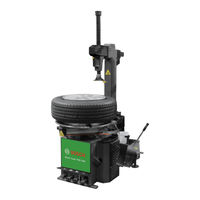
Bosch Start Line TCE 420 Repair Instructions (82 pages)
Tyre changing machines
Brand:
Bosch
| Category:
Tyre Changers
| Size: 1.58 MB
Table of Contents
Deutsch
4
Table of Contents
4
1 Verwendete Symbolik
5
In der Dokumentation
5
Warnhinweise - Aufbau und Bedeutung
5
Symbole - Benennung und Bedeutung
5
Auf dem Produkt
5
2 Allgemeine Hinweise
5
3 Regelmäßige Wartung
6
Verwendung und Wartung des Druckluftreglers
6
Muttern an Gerät in Regelmäßigen Zeitabständen Anziehen
7
Dämpfer an den Pedalventilen in Regelmäßigen Zeitabständen Reinigen
7
4 Einrichtung des Geräts
8
Winkel des Montagekopfes Einstellen
8
Sechskant-Sicherungsplatte Justieren
8
Vierkant-Sicherungsplatte Justieren
8
Vierkantwellenrolle Justieren
8
Feststellschrauben und -Muttern Unten am Schwenkarm Justieren
9
Stellung der Pedalventilstange des Wulstabdrückzylinders Einstellen
9
Stellung der Pedalventilstange des Drehtellerzylinders Einstellen
9
Stellung der Pedalventilstange des Schwenkzylinders Einstellen
9
Dämpfer Oben am Schwenkzylinderventil Einstellen
10
Stellung der Spannklauen Justieren
10
Sicherungslasche des Wulstabdrückzylinders Justieren
11
Motorriemen Einstellen
11
Stellung des Schalters Justieren
11
5 Austausch von Komponenten
12
Drehtellerzylinder und Dichtungsringe Austauschen
12
Drehtellerzylinder Austauschen
12
Äußere Dichtungsringe Ersetzen
12
Innere Dichtungsringe Ersetzen
12
Wulstabdrückzylinder und Dichtungsringe Ersetzen
12
Wulstabdrückzylinder Wechseln
12
Schwenkzylinder und Dichtungsringe Austauschen
13
Schwenkzylinder Austauschen
13
Dichtungsringe IM Zylinder Ersetzen
13
Sperrzylinder und Dichtungsringe der Sechskantwelle Ersetzen
13
Sperrzylinder und Dichtungsringe der Vierkantwelle Ersetzen
13
Ventilgriff und Dichtungsringe Ersetzen
13
Luftverteiler und Dichtungsringe Ersetzen
14
Pedalventilbaugruppe und Dichtungsringe Ersetzen
14
Auslassventil und Dichtungsringe Ersetzen
14
Auslassventil Ersetzen
14
Dichtungsringe Ersetzen
14
Getriebe Ersetzen
14
Schalter Wechseln
15
Kondensator Austauschen
15
Motor Austauschen
15
Pedalspannfeder oder Torsionsfeder Ersetzen
15
6 Fehlersuche und -Behebung
16
Drehteller Dreht sich nicht
16
Schwaches Drehmoment des Drehtellers
16
Spannklauen Bewegen sich nicht oder nicht ohne Widerstand
16
Spannklauen Bewegen sich von selbst
17
Spannklauen können die Felge nicht Festhalten
17
Montagekopf Verschleißt zu Schnell
17
Stellung des Montagekopfes nach der Rückkehr des Schwenkarms Verändert
17
Zylinder Undicht
17
Getriebe Dreht sich nicht oder unter Großer Geräuschentwicklung
17
Unregelmäßige Auf- und Abbewegung der Sechskantwelle
17
Pedal Kehrt nicht Zurück
17
Schwenkarm Bewegt sich nicht oder zu Langsam
18
Wulstabdrückschaufel Bewegt sich zu Langsam
18
Wulstabdrückung ohne Kraft
18
7 Umgang mit Öl
19
8 Übersichtsschaltplan Pneumatik
20
9 Stromlaufplan
21
English
24
1 Symbols Used
25
In the Documentation
25
Warning Notices - Structure and Meaning
25
Symbols in this Documentation
25
On the Product
25
2 General Principles
25
3 Maintenance Routine
26
Air Regulator Usage and Maintain
26
Tighten the Nuts on Equipment at Regular Intervals
27
Clean the Silencer on Pedal Valves at Regular Intervals
27
4 Equipment Adjustment
28
Adjust the Angle of Demounting Head
28
Adjust the Hex Locking Plate
28
Adjust the Square Locking Plate
28
Adjust the Square Shaft Roller
28
Adjust Fixing Bolts and Nuts at the Lower End of Tilt Arm
29
Adjust the Position of Pedal Valve Rod for Bead Break Cylinder
29
Adjust the Position of Pedal Valve Rod for Turntable Cylinder
29
Adjust the Position of Pedal Valve Rod for Tilt Cylinder
29
Adjust the Silencer at Top of Tilt Cylinder Valve
30
Adjust the Position of Clamps
30
Adjust the Fixing Sleeve of Bead Break Cylinder
31
Adjust the Motor Belt
31
Adjust the Position of Switch
31
5 Change the Components
32
Change Turntable Cylinder and Sealing Rings
32
Change Turntable Cylinder
32
Change Outside Sealing Rings
32
Change Inside Sealing Rings
32
Change Bead Break Cylinder and Sealing Rings
32
Change Bead Break Cylinder
32
Change Tilt Cylinder and Sealing Rings
33
Change Tilt Cylinder
33
Change the Sealing Rings in Cylinder
33
Change Hex Shaft Locking Cylinder and Sealing Rings
33
Change Square Shaft Locking Cylinder and Sealing Rings
33
Change the Handle Valve and Sealing Rings
33
Change the Air Guider and Sealing Rings
34
Change the Pedal Valve Assembly and Sealing Rings
34
Change Exhaust Valve and Sealing Rings
34
Change the Exhaust Valve
34
Change Sealing Rings
34
Change Gearbox
34
Change the Switch
35
Change the Capacitor
35
Change Motor
35
Change the Pedal Tension Spring or Torsion Spring
35
6 Trouble
36
Turntable Not Rotate
36
Powerless Turntable Torsion Power
36
Clamps Not Move or Moves Not Smoothly
36
The Clamps Move Automatically
37
The Clamps Cannot Fix the Rim
37
Demounting Head Is Wear and Tear too Fast
37
The Position of Demounting Head Has Change When Tilt Arm Returns Back
37
Leakage in Cylinder
37
The Gearbox Not Rotate or Has Big Noise
37
Hex Shaft Moves up and down Not Smoothly
37
Pedal Cannot Return Back
37
Tilt Arm Cannot Tilt or Tilt Slowly
37
Bead Break Blade Moves Slowly
38
Powerless Bead Break Power
38
7 Oil Usage
38
8 Pneumatic Schematic Dia- Gram
39
9 Circuit Diagram
40
Español
42
1 Símbolos Empleados
43
En la Documentación
43
Advertencias: Estructura y Significado
43
Símbolos en Esta Documentación
43
En el Producto
43
2 Indicaciones Generales
43
3 Mantenimiento Regular
44
Uso y Mantenimiento del Regulador de Aire Comprimido
44
Apretar las Tuercas del Equipo a Intervalos Regulares
45
Limpiar el Amortiguador Situado en las Válvulas del Pedal a Intervalos Regulares
45
4 Instalación de la Máquina
46
Ajustar el Ángulo del Cabezal de Montaje
46
Ajustar la Placa de Seguridad Hexagonal
46
Ajustar la Placa de Seguridad Cuadrada
46
Ajustar la Rueda del Eje Cuadrado
46
Ajustar Los Tornillos y Tuercas de Fijación en la Parte Inferior del Brazo Giratorio
47
Ajustar la Posición del Vástago de la Válvula del Pedal del Cilindro Destalonador
47
Ajuste de la Posición del Vástago de la Válvula del Pedal del Cilindro de la Base Giratoria
47
Ajuste de la Posición del Vástago de la Válvula del Pedal del Cilindro Destalonador
47
Ajustar el Amortiguador Superior Situado en la Válvula del Cilindro Oscilante
48
Ajustar la Posición de las Garras Tensoras
48
Ajustar la Lengüeta de Seguridad del Cilindro Destalonador
49
Ajustar la Correa del Motor
49
Ajustar la Posición del Interruptor
49
5 Sustitución de Componentes
50
Cambiar el Cilindro de la Base Giratoria y las Juntas Anulares
50
Cambiar el Cilindro de la Base Giratoria
50
Sustituir la Junta Anular Exterior
50
Sustitución de la Junta Anular Interior
50
Sustitución del Cilindro Destalonador y de las Juntas Anulares
50
Cambiar el Cilindro Destalonador
50
Sustitución del Cilindro Oscilante y de las Juntas Anulares
51
Sustitución del Cilindro Oscilante
51
Sustituir las Juntas Anulares en el Cilindro
51
Sustitución del Cilindro de Bloqueo y de las Juntas Anulares del Eje Hexagonal
51
Sustitución del Cilindro de Bloqueo y de las Juntas Anulares del Eje Cuadrado
51
Sustitución del Mango de la Válvula y de las Juntas Anulares
51
Sustitución del Distribuidor de Aire y de las Juntas Anulares
52
Sustitución del Módulo de Válvulas del Pedal y de las Juntas Anulares
52
Sustitución de la Válvula de Descarga y de las Juntas Anulares
52
Sustituir la Válvula de Descarga
52
Sustituir las Juntas Anulares
52
Sustitución de la Transmisión
52
Scambiar el Interruptor
53
Cambiar el Condensador
53
Cambiar el Motor
53
Sustituir el Resorte Tensor del Pedal O el Resorte de Torsión
53
6 Búsqueda y Reparación de Errores
54
La Base Giratoria no Gira
54
Par de Apriete Débil de la Base Giratoria
54
Las Garras Tensoras no Se Mueven O no lo Hacen sin Resistencia
54
Las Garras Tensoras Se Mueven por sí Solas
55
Las Garras Tensoras no Sujetan la Llanta
55
El Cabezal de Montaje Se Desgasta con Demasiada Rapidez
55
Se Ha Modificado la Posición del Cabezal de Montaje Después del Retorno del Brazo Giratorio
55
El Cilindro no es Estanco
55
La Transmisión no Gira O lo Hace Generando Ruido Intenso
55
Movimiento de Avance y Retroceso Irregular del Eje Hexagonal
55
El Pedal no Vuelve
55
El Brazo Giratorio no Se Mueve O lo Hace con Demasiada Lentitud
56
La Pala de Destalonamiento Se Mueve con Demasiada Lentitud
56
Destalonamiento sin Fuerza
56
7 Manejo del Aceite
57
8 Esquema Sinóptico de Los Circuitos de Conexión del Sistema Neumático
58
9 Esquema Eléctrico
59
Italiano
62
1 Simboli Utilizzati
63
Nella Documentazione
63
Indicazioni DI Avvertimento
63
Struttura E Significato
63
Simboli Nella Presente Documentazione
63
Sul Prodotto
63
2 Avvertenze Generali
63
3 Manutenzione Regolare
64
Utilizzo E Manutenzione del Regolatore Dell'aria Compressa
64
Serrare I Dadi Sull'apparecchio a Intervalli Regolari
65
Pulire Gli Ammortizzatori Sulle Valvole del Pedale a Intervalli Regolari
65
4 Allestimento Dell'apparecchio
66
Impostare L'angolare Dell'utensile DI Montaggio
66
Regolare la Piastra DI Sicurezza Esagonale
66
Regolare la Piastra DI Sicurezza Quadrata
66
Regolare Il Rullo Dell'albero Quadrato
66
Regolare Le Viti E I Dadi DI Fissaggio in Basso Sul Braccio Orientabile
67
Impostare la Posizione Dell'asta Della Valvola del Pedale del Cilindro Stallonatore
67
Impostare la Posizione Dell'asta Della Valvola del Pedale del Cilindro del Piatto Rotante
67
Impostare la Posizione Dell'asta Della Valvola del Pedale del Cilindro Orientabile
67
Impostare L'ammortizzatore in Alto Sulla Valvola del Cilindro Orientabile
68
Regolare la Posizione Delle Griffe DI Bloccaggio
68
Regolare la Linguetta DI Sicurezza del Cilindro Stallonatore
69
Impostare la Cinghia del Motore
69
Regolare la Posizione Dell'interruttore
69
5 Sostituzione Dei Componenti
70
Sostituire Il Cilindro del Piatto Rotante E Gli
70
Anelli DI Tenuta
70
Sostituire Il Cilindro del Piatto Rotante
70
Sostituire Gli Anelli DI Tenuta Esterni
70
Sostituire Gli Anelli DI Tenuta Interni
70
Sostituire Il Cilindro Stallonatore E Gli Anelli DI Tenuta
70
Sostituire Il Cilindro Stallonatore
70
Sostituire Il Cilindro Orientabile E Gli Anelli DI Tenuta
71
Change Tilt Cylinder
71
Sostituire Gli Anelli DI Tenuta Nel Cilindro
71
Sostituire Il Cilindro DI Bloccaggio E Gli Anelli DI Tenuta Dell'albero Esagonale
71
Sostituire Il Cilindro DI Bloccaggio E Gli Anelli DI Tenuta Dell'albero Quadrato
71
Sostituire la Maniglia Della Valvola E Gli Anelli DI Tenuta
71
Sostituire Il Distributore Dell'aria E Gli Anelli DI Tenuta
72
Sostituire Il Gruppo Valvole del Pedale E Gli Anelli DI Tenuta
72
Sostituire la Valvola DI Scarico E Gli Anelli DI Tenuta
72
Sostituire la Valvola DI Scarico
72
Sostituire Gli Anelli DI Tenuta
72
Sostituire Il Riduttore
72
Sostituire L'interruttore
73
Sostituire Il Condensatore
73
Sostituire Il Motore
73
Sostituire la Molla Tenditrice del Pedale E la Molla DI Torsione
73
6 Ricerca E Rimozione Degli Errori
74
Il Piatto Rotante Non Gira
74
Coppia Debole del Piatto Rotante
74
Le Griffe DI Bloccaggio Non si Muovono O Non Senza Resistenza
74
Le Griffe DI Bloccaggio si Muovono Autonomamente
75
Le Griffe DI Bloccaggio Non Riescono a Bloccare Il Cerchione
75
L'utensile DI Montaggio si Usura Troppo Velocemente
75
Posizione Dell'utensile DI Montaggio Dopo Il Ritorno del Braccio Orientabile Modificata
75
Cilindro Non a Tenuta
75
Il Riduttore Non Ruota O solo con Grande Rumorosità
75
Sollevamento E Abbassamento Irregolari Dell'albero Esagonale
75
Il Pedale Non Torna Indietro
75
Il Braccio Orientabile Non Ruota O Ruota Troppo Lentamente
76
La Paletta Dello Stallonatore si Muove Troppo Lentamente
76
Stallonatura Senza Forza
76
7 Gestione Dell'olio
77
8 Schema Panoramico Dell'impianto Pneumatico
78
9 Schema Elettrico
79
Advertisement
Related Products
Bosch TCE 4540
Bosch TCE 4460
Bosch TCE 5310
Bosch TCE 330
Bosch TCE 230
Bosch TCE 260
Bosch TCE 4510
Bosch TCE 5210
Bosch TCE 60
Bosch TCE 4225
Bosch Categories
Dishwasher
Washer
Oven
Power Tool
Dryer
More Bosch Manuals
Login
Sign In
OR
Sign in with Facebook
Sign in with Google
Upload manual
Upload from disk
Upload from URL