Sign In
Upload
Manuals
Brands
ABB Manuals
Network Hardware
DPU2000R
ABB DPU2000R Manuals
Manuals and User Guides for ABB DPU2000R. We have
1
ABB DPU2000R manual available for free PDF download: Manual
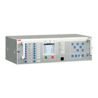
ABB DPU2000R Manual (66 pages)
Modbus Point List Mitigation
Brand:
ABB
| Category:
Network Hardware
| Size: 1.61 MB
Table of Contents
Table of Contents
7
Introduction
13
This Manual
13
Intended Audience
13
Document Revision History
13
Related Documentation
13
Symbols and Conventions
14
Safety Indication Symbols
14
Modbus Point List Mapping Mitigations
15
Overview
15
Modbus Point List Mapping Mitigations
16
0X Registers
17
Function Code 1 (Read Coil Status)
17
Logical Output Block (Single-Bit Data)
17
Table 1. Mitigations of Modbus Registers Mapping for the Logical Output Points in Single-Bit Block
17
0X Registers
18
Physical Output Block (Single-Bit Data)
24
Table 2. Mitigations of Modbus Registers Mapping for the Physical Output Points in Single-Bit Block
24
Logical Output Block (Double-Bit Data with Momentary Change Detection)
25
Physical Output Block (Double-Bit Data with Momentary Change Detection)
25
Table 3. Mitigations of Modbus Registers Mapping for the Logical Output Points in Double-Bit Block
25
Table 4. Mitigations of Modbus Registers Mapping for the Physical Output Points in Double-Bit Block
26
1X Registers
27
Function Code 2 (Read Input Status)
27
Logical Input Block (Single-Bit Data)
27
Table 5. Mitigations of Modbus Registers Mapping for the Logical Input Block in Single-Bit Block
27
Physical Input Block (Single-Bit Data)
30
Table 6. Mitigations of Modbus Registers Mapping for the Physical Input Block in Single-Bit Block
30
1X Registers
30
Logical Input Block (Double-Bit Data with Momentary Change Detection)
31
Table 7. Mitigations of Modbus Registers Mapping for the Logical Input Block in Double Bit Block
31
Physical Input Block (Double-Bit Data with Momentary Change Detection)
32
Table 8. Mitigations of Modbus Registers Mapping for the Physical Input Block in Double-Bit Block
32
4X Registers
33
Function Code 3 (Read Holding Register)
33
User Programmable Register Block (UDR)
33
Example of Remapping a Discrete Signal to a UDR
33
Figure 1. Snapshot of CMT in UDR View
33
Table 9. Mitigations of Modbus User Defined Registers (UDR)
33
Example of Remapping an Analog Register to UDR
34
Figure 2. Snapshot of 51P Remapped to 40001:00
34
Table 10. Example and Explanation of One Digital Signal (51P) in
34
Figure 3. UDR Multiplicative Scaling Factor for "Ld0.Cmmxu1.A.phsa.instcval.mag.f
35
System Status/Configuration Block
36
Table 11. Mitigations of Modbus System Status/Configuration Block
36
Figure 4. UDR Divisor Scaling Factor to Convert a Voltage Reading from Pu to Primary KV
36
RMS Load Current/Angular Values Block
39
Table 12. Mitigations of Modbus Mappings for RMS Load Current/Angular Values Block
39
Figure 5. Snapshot on Scaling Load Current a from CMT to Read Primary Current in Ampere
39
4X Registers
40
RMS Demand Current/Real and Reactive Power Values Block
42
Table 13. Mitigation of Modbus Mappings for RMS Demand Current/Real and Reactive Power Values Block
42
RMS Peak Demand Current/Real, Reactive Power Values and Time Stamps Block
43
Table 14. Mitigation of Modbus Mappings for Peak Demand Current/Real, Reactive Power Values and Time Stamps Blocks
43
RMS Minimum Demand Current/Real, Reactive Power Values and Time Stamps
44
Table 15. Mitigation of Modbus Mappings for Minimum Demand Current/Real, Reactive Power Values and Time Stamps Block
45
Counters Block
46
Table 16. Mitigation of Modbus Mappings for Counter Block
46
Physical and Logical Input / Output State Block
47
Table 17. Mitigation of Modbus Physical and Logical Input/Output State Block
47
Function Code 16 (Preset Multiple Register)
48
Control Command Addresses Change
48
Control Command Format Change
48
Control Mask Block (Read and Write)
48
Table 18. Uniformed Control Command Format in REF615R
48
Table 19. Mitigation of Modbus Mapping for Control Mask Block
48
Function Code 23 (Read/Write 4X Registers)
51
Fault Record
51
Table 20. Mitigation of Modbus Mapping for Fault Records Block
52
Operation Records
53
Table 21. Mitigation of Modbus Mapping for Operation Records
54
Table 22. One Example of Modbus Event Record Value
54
Figure 6. Snapshot of Using CMT to Enable Modbus Event on Coil
55
6X Registers
57
Selected PCM ACT Logic Examples or Explanations
59
Logical Output Points
59
Three Phase under Voltage Trip (27-3P)
59
Instantaneous 3 Phase Over-Current Alarm Disabled (50-3D)
60
Logical Input ACT Logic Selected Examples
60
Enable Phase over Current Protection for All Phase Elements Except 50P3 (PH3)
60
Enable Ground over Current Protection for All Ground Elements Except 50N-3(GRD)
60
Figure 7. Example of Create Seal in Point for 46-1 Trip
60
Enable 50P-1 and 50N-1 (50-1)
61
Enable 50P-2 and 50N-2 (50-2)
61
Enable 50P-3 and 50N-3 (50-3)
61
Enable Alternate 1 Settings (ALT1)
61
Enable Alternate 2 Settings (ALT2)
61
The Seal in Points (Latch) Using SRGAPC Give on Example
60
1 St Instantaneous Over-Current Distance Alarm (50-1D)
59
2 Nd Instantaneous Over-Current Distance Alarm (50-2D)
59
Ground Over-Current Disabled Alarm (GRD-D)
59
Phase Over-Current Disabled Alarm (PH3-D)
59
Glossary
63
Advertisement
Advertisement
Related Products
ABB Conceptpower DPA 500
ABB CONCEPTPOWER CLASSIC DPA-50
ABB CONCEPTPOWER UPGRADE DPA-250
ABB CONCEPTPOWER TRIPLE DPA-150
ABB DPA Upscale RI Series
ABB DPA 250 S4
ABB DPU 1500R
ABB DP7-S-611
ABB DP7-S-625
ABB DCS880 H8
ABB Categories
Industrial Equipment
Controller
Measuring Instruments
Battery Charger
DC Drives
More ABB Manuals
Login
Sign In
OR
Sign in with Facebook
Sign in with Google
Upload manual
Upload from disk
Upload from URL