Sony SLV-E580EE Service Manual
Hide thumbs
Also See for SLV-E580EE:
- Operating instructions manual (56 pages) ,
- Service manual (10 pages) ,
- Service manual (79 pages)
Table of Contents
Advertisement
SLV-E580EE/E580EG/E630AE/E630NP/E727VC/E730B/E730EX/E730NC/E730NP/
QQ
E730UX/E730VC/E730VP/E735B/E735NC/E735VC/E780EE/E780EG/E780EN
3 7 63 1515 0
SERVICE MANUAL
S MECHANISM
G
• Refer to the SERVICE MANUAL of VHS MECHANICAL
ADJUSTMENTS VI for MECHANICAL ADJUSTMENTS.
(9-921-647-11)
TE
L 13942296513
* The abbreviations of E580, E630, E727, E730, E735, E780 con-
tained in this service manual are indicated when these models
are common to all their corresponding models as given below.
Abbreviated
model name
E580EE
E580EG
All model
names
SLV-
www
.
MICROFILM
http://www.xiaoyu163.com
RMT-V220B/V221D/V223/V223A/V223B/V224/V224C
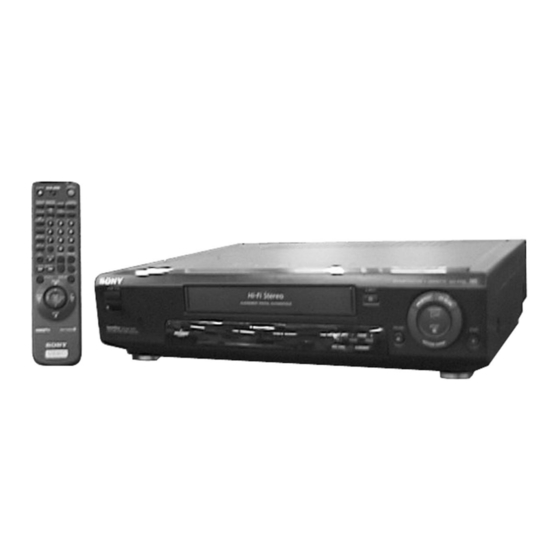
Photo: SLV-E780
E580
E630
E630AE
E630NP
x
ao
y
i
http://www.xiaoyu163.com
8
Q Q
3
6 7
1 3
E727
E730
E727VC
E730B
E730EX
E730NC
E730NP
E730UX
E730VC
E730VP
VIDEO CASSETTE RECORDER
u163
.
2 9
9 4
2 8
AEP Model
French Model
East European Model
SLV-E580EE/E780EE
Middle European Model
SLV-E580EG/E780EG/E780EN
North European Model
SLV-E730NC/E735NC
Irish Model
Spanish Model
SLV-E630NP/E730NP
German Model
SLV-E727VC/E730VC/E730VP/E735VC
1 5
0 5
8
2 9
9 4
E735
E735B
E780EE
E735NC
E780EG
E735VC
E780EN
m
co
9 9
SLV-E630AE
SLV-E730B/735B
SLV-E730EX
UK Model
SLV-E730UX
2 8
9 9
E780
Advertisement
Table of Contents

Related Manuals for Sony SLV-E580EE


Summary of Contents for Sony SLV-E580EE
- Page 1 SLV-E580EE/E580EG/E630AE/E630NP/E727VC/E730B/E730EX/E730NC/E730NP/ E730UX/E730VC/E730VP/E735B/E735NC/E735VC/E780EE/E780EG/E780EN 3 7 63 1515 0 RMT-V220B/V221D/V223/V223A/V223B/V224/V224C SERVICE MANUAL AEP Model SLV-E630AE French Model SLV-E730B/735B East European Model SLV-E580EE/E780EE Middle European Model SLV-E580EG/E780EG/E780EN North European Model SLV-E730NC/E735NC Photo: SLV-E780 Irish Model SLV-E730EX S MECHANISM Spanish Model SLV-E630NP/E730NP UK Model SLV-E730UX •...
- Page 2 http://www.xiaoyu163.com 3 7 63 1515 0 SPECIFICATIONS System Inputs and outputs General Ú LINE-1 (TV) Channel coverage Power requirements E580EE/E780EE: 21-pin 220 – 240 V AC, 50 Hz VHS E2 to E12, R1 to R12 Video input: pin 20 Power consumption UHF E21 to E69, R21 to R69 Audio input: pins 2 and 6 CATV S1 to S41, S01 to S05...
-
Page 3: Feature Difference
LINE WITH MARK ! ON THE SCHEMATIC DIAGRAMS AND IN THE PARTS LIST ARE CRITICAL TO SAFE OPERATION. REPLACE THESE COMPONENTS WITH SONY PARTS WHOSE PART NUMBERS APPEAR AS SHOWN IN THIS MANUAL OR IN SUPPLEMENTS PUB- LISHED BY SONY. -
Page 4: Table Of Contents
http://www.xiaoyu163.com 3 7 63 1515 0 TABLE OF CONTENTS Section Title Page Section Title Page Feature Difference ..............3 Service Note ................5 5-1. System Control-Video/RP Block Interface (MA-315 board IC161) ..........5-1 5-2. System Control-Servo Peripheral Circuit Interface GENERAL (MA-315 board IC161) .......... -
Page 5: Service Note
http://www.xiaoyu163.com SERVICE NOTE 3 7 63 1515 0 1. DISASSEMBLY • This set can be disassembled in the order shown below. Note: Pages in indicate pages in the SERVICE MANUAL. Pages in indicate pages in the VHS MECHANICAL ADJUSTMENT MANUAL VI. Upper Case (Page 2-1) -
Page 6: General
http://www.xiaoyu163.com SLV-E580/E630/E727/E730/E735/E780 This section is extracted from SLV- SECTION 1 3 7 63 1515 0 E727VC, SLV-E730NC/NP/VC/VP, GENERAL SLV-E735NC/VC instruction manual. L 13942296513 u163 http://www.xiaoyu163.com... - Page 7 http://www.xiaoyu163.com 3 7 63 1515 0 L 13942296513 u163 http://www.xiaoyu163.com...
- Page 8 http://www.xiaoyu163.com 3 7 63 1515 0 L 13942296513 u163 http://www.xiaoyu163.com...
- Page 9 http://www.xiaoyu163.com 3 7 63 1515 0 L 13942296513 u163 http://www.xiaoyu163.com...
- Page 10 http://www.xiaoyu163.com 3 7 63 1515 0 L 13942296513 u163 http://www.xiaoyu163.com...
- Page 11 http://www.xiaoyu163.com 3 7 63 1515 0 L 13942296513 u163 http://www.xiaoyu163.com...
- Page 12 http://www.xiaoyu163.com 3 7 63 1515 0 L 13942296513 u163 http://www.xiaoyu163.com...
- Page 13 http://www.xiaoyu163.com 3 7 63 1515 0 L 13942296513 u163 http://www.xiaoyu163.com...
- Page 14 http://www.xiaoyu163.com 3 7 63 1515 0 L 13942296513 u163 http://www.xiaoyu163.com...
- Page 15 http://www.xiaoyu163.com 3 7 63 1515 0 L 13942296513 u163 1-10 http://www.xiaoyu163.com...
- Page 16 http://www.xiaoyu163.com 3 7 63 1515 0 L 13942296513 u163 1-11 http://www.xiaoyu163.com...
- Page 17 http://www.xiaoyu163.com 3 7 63 1515 0 L 13942296513 u163 1-12 http://www.xiaoyu163.com...
- Page 18 http://www.xiaoyu163.com 3 7 63 1515 0 L 13942296513 u163 1-13 http://www.xiaoyu163.com...
- Page 19 http://www.xiaoyu163.com 3 7 63 1515 0 L 13942296513 u163 1-14 http://www.xiaoyu163.com...
- Page 20 http://www.xiaoyu163.com 3 7 63 1515 0 L 13942296513 u163 1-15 1-15 E http://www.xiaoyu163.com...
-
Page 21: Disassembly
http://www.xiaoyu163.com SLV-E580/E630/E727/E730/E735/E780 SECTION 2 3 7 63 1515 0 DISASSEMBLY Note: Follow the disassembly procedure in the numerical order given. 2-1. UPPER CASE REMOVAL 2-3. FRONT PANEL SECTION REMOVAL 3 Upper case 1 Connector (CN161) 1 Two screws (E580/E780) (Case3 TP2) 1 Flat wire (CN164) 2 Two screws... -
Page 22: Board Removal
http://www.xiaoyu163.com 3 7 63 1515 0 2-5. RP-230, SE-68 BOARD REMOVAL 2-7. MA-315, SR-826 BOARD REMOVAL 2 Two screws 6 Three screws (B3) (B3) 4 RP-230 board Tuner unit 7 MA-315 board 5 Screw (B3) 3 Two connector 6 SE-68 board (CN305, 306) (E730B/E735B) 1 Flexible board... -
Page 23: Internal Views
http://www.xiaoyu163.com 3 7 63 1515 0 2-8. INTERNAL VIEWS Drum assembly (M901) (DZH-85A-R) 1-759-371-11 (E580) Drum assembly (M901) (DZH-86A-R) 1-759-373-11 (EXCEPT E580/E730B/E735B) Drum assembly (M901) (DZH-98A-R) 1-759-557-11 (E730B/E735B) FE head 1-500-144-11 Q101 Tape top sensor 8-729-043-84 Q100 Tape end sensor 8-729-043-84 L 13942296513 D102... -
Page 24: Circuit Boards Location
http://www.xiaoyu163.com 3 7 63 1515 0 2-9. CIRCUIT BOARDS LOCATION MA-315 VIDEO, AUDIO, IO, SERVO/SYSTEM CONTROL, TUNER RP-230 (HEAD AMP) SE-68 (E730B/E735B) (SECAM) FR-127 FL DRIVER, MODE CONTROL L 13942296513 SR-825 DM-72 (POWER SUPPLY) (MODE CONTROL) u163 2-4 E http://www.xiaoyu163.com... - Page 25 http://www.xiaoyu163.com 3 7 6 3 1 5 1 5 0 1 3 9 4 2 2 9 6 5 1 3 w w w u 1 6 3 http://www.xiaoyu163.com...
- Page 26 http://www.xiaoyu163.com 3 7 6 3 1 5 1 5 0 1 3 9 4 2 2 9 6 5 1 3 w w w u 1 6 3 http://www.xiaoyu163.com...
- Page 27 http://www.xiaoyu163.com 3 7 6 3 1 5 1 5 0 1 3 9 4 2 2 9 6 5 1 3 w w w u 1 6 3 http://www.xiaoyu163.com...
- Page 28 http://www.xiaoyu163.com 3 7 6 3 1 5 1 5 0 1 3 9 4 2 2 9 6 5 1 3 w w w u 1 6 3 http://www.xiaoyu163.com...
- Page 29 http://www.xiaoyu163.com 3 7 6 3 1 5 1 5 0 1 3 9 4 2 2 9 6 5 1 3 w w w u 1 6 3 http://www.xiaoyu163.com...
- Page 30 http://www.xiaoyu163.com 3 7 6 3 1 5 1 5 0 1 3 9 4 2 2 9 6 5 1 3 w w w u 1 6 3 http://www.xiaoyu163.com...
- Page 31 http://www.xiaoyu163.com 3 7 6 3 1 5 1 5 0 1 3 9 4 2 2 9 6 5 1 3 w w w u 1 6 3 http://www.xiaoyu163.com...
- Page 32 http://www.xiaoyu163.com 3 7 6 3 1 5 1 5 0 1 3 9 4 2 2 9 6 5 1 3 w w w u 1 6 3 http://www.xiaoyu163.com...
- Page 33 http://www.xiaoyu163.com 3 7 6 3 1 5 1 5 0 1 3 9 4 2 2 9 6 5 1 3 w w w u 1 6 3 http://www.xiaoyu163.com...
- Page 34 http://www.xiaoyu163.com 3 7 6 3 1 5 1 5 0 1 3 9 4 2 2 9 6 5 1 3 w w w u 1 6 3 http://www.xiaoyu163.com...
- Page 35 http://www.xiaoyu163.com w w w http://www.xiaoyu163.com...
- Page 36 http://www.xiaoyu163.com w w w http://www.xiaoyu163.com...
- Page 37 http://www.xiaoyu163.com 3 7 6 3 1 5 1 5 0 1 3 9 4 2 2 9 6 5 1 3 w w w u 1 6 3 http://www.xiaoyu163.com...
- Page 38 http://www.xiaoyu163.com 3 7 6 3 1 5 1 5 0 1 3 9 4 2 2 9 6 5 1 3 w w w u 1 6 3 http://www.xiaoyu163.com...
- Page 39 http://www.xiaoyu163.com 3 7 6 3 1 5 1 5 0 1 3 9 4 2 2 9 6 5 1 3 w w w u 1 6 3 http://www.xiaoyu163.com...
- Page 40 http://www.xiaoyu163.com 3 7 6 3 1 5 1 5 0 1 3 9 4 2 2 9 6 5 1 3 w w w u 1 6 3 http://www.xiaoyu163.com...
- Page 41 http://www.xiaoyu163.com 3 7 6 3 1 5 1 5 0 1 3 9 4 2 2 9 6 5 1 3 w w w u 1 6 3 http://www.xiaoyu163.com...
- Page 42 http://www.xiaoyu163.com 3 7 6 3 1 5 1 5 0 1 3 9 4 2 2 9 6 5 1 3 w w w u 1 6 3 http://www.xiaoyu163.com...
- Page 43 http://www.xiaoyu163.com 3 7 6 3 1 5 1 5 0 1 3 9 4 2 2 9 6 5 1 3 w w w u 1 6 3 http://www.xiaoyu163.com...
- Page 44 http://www.xiaoyu163.com 3 7 6 3 1 5 1 5 0 1 3 9 4 2 2 9 6 5 1 3 w w w u 1 6 3 http://www.xiaoyu163.com...
- Page 45 http://www.xiaoyu163.com 3 7 6 3 1 5 1 5 0 1 3 9 4 2 2 9 6 5 1 3 w w w u 1 6 3 http://www.xiaoyu163.com...
-
Page 46: System Control-Video/Rp Block Interface (Ma-315 Board Ic161)
http://www.xiaoyu163.com 3 7 6 3 1 5 1 5 0 5-1. SYSTEM CONTROL – VIDEO/RP BLOCK INTERFACE (MA-315 BOARD IC161) STOP/ TAPE TAPE REC • Signal Pin No. LOADING UNLOADING PAUSE MA-315 ∗1 ∗1 ∗1 ∗1 ∗1 ∗1 RF SWP IC161!•... - Page 47 http://www.xiaoyu163.com 5-3. SYSTEM CONTROL – MECHANISM BLOCK INTERFACE (MA-315 BOARD IC161) 3 7 6 3 1 5 1 5 0 TAPE TAPE CASSETTE CASSETTE Signal Pin No. EJECTED THREAD- UNTHREAD- STOP LOADING UNLOADING MA-315 IC161%• MA-315 MODE 1 – – IC161@ª...
-
Page 48: System Control-System Control Peripheral Circuit Interface (Ma-315 Board Ic161)
http://www.xiaoyu163.com 3 7 6 3 1 5 1 5 0 5-4. SYSTEM CONTROL – SYSTEM CONTROL PERIPHERAL CIRCUIT INTERFACE (MA-315 BOARD IC161) Signal Pin No. I/O level MA-315 RESET Normally “H”, “L” when service interruption is detected or restored. IC161$£ MA-315 I2C DATA VIDEO Serial communication data to video microprocessor. -
Page 49: Servo/System/Tuner/Timer Control Microprocessor Pin Function (Ma-315 Board Ic161)
http://www.xiaoyu163.com 5-6. SERVO/SYSTEM/TIMER/TUNER CONTROL MICROPROCESSOR PIN FUNCTION (MA-315 BOARD IC161) 3 7 6 3 1 5 1 5 0 Pin No. Pin name Function Pin No. Pin name Function N.C. – Not used C CLOCK VIDEO, C+ C clock (VIDEO, C+) DEST 0 Destination judgement 0 C DATA VIDEO, C+... -
Page 50: Error Code
http://www.xiaoyu163.com SLV-E580/E630/E727/E730/E735/E780 SECTION 6 3 7 63 1515 0 ERROR CODES Table 6-2. Mode Codes in Case of Error This set displays an error code, and a mode code in case of error on the display tube, if the operation stopped by error. Code Description The following provides description concerned. -
Page 51: Adjustments
http://www.xiaoyu163.com SLV-E580/E630/E727/E730/E735/E780 3 7 63 1515 0 SECTION 7 ADJUSTMENTS 2-1-2. Connection During the adjustment, see the Parts Arrangement Unless otherwise specified, connect and adjust the measuring in- Diagram for Adjustment on page 7-8. struments as shown in the following diagram. 7-1. -
Page 52: Specified I/O Level And Impedance
http://www.xiaoyu163.com 3 7 63 1515 0 2-1-5. Specified I/O Level and Impedance 2-2. POWER SUPPLY ADJUSTMENT Input/output terminal Video inputs LINE IN : phono jacks 2-2-1. Power Supply Check EURO-AV : 21-pin (Pin @º) 1 Vp-p, 75 Ω, (SR-825 BOARD) unbalanced, sync nagative Mode Audio inputs... -
Page 53: Servo System Adjustment
http://www.xiaoyu163.com 3 7 63 1515 0 2-3. SERVO SYSTEM Adjustment 2-4. VIDEO SYSTEM ADJUSTMENT Adjust the video system in the following sequence as a rule. The 2-3-1. RF Switching Position Adjustment color video signal supplied from the pattern generator is used as a (RP-230 Board) video input signal for video system adjustment in the recording mode. - Page 54 http://www.xiaoyu163.com 3 7 63 1515 0 2-4-2. Recording Chroma Level Check 2-4-4. X’tal Oscillation Frequency Check (MA-315 Board) (MA-315) Purpose: Purpose: Check the chroma signal level after passing through the Y/C sepa- Confirm that the fsc is correct. rating circuit. If shifted, the image is roughened and another color may appear Mode on the edges.
-
Page 55: Audio System Adjustment
http://www.xiaoyu163.com 3 7 63 1515 0 2-5. AUDIO SYSTEM ADJUSTMENTS RF SWP • Adjust both Lch and Rch. [Connection] Audio Audiolevel meter or generator distortion meter 600 Ω 47 kΩ Attenuator AUDIO LINE IN Feed signal both AUDIO LINE OUT channelssimultaneously. -
Page 56: Normal Audio System Adjustment
http://www.xiaoyu163.com 3 7 63 1515 0 3. Overall Level Characteristic and Distortion Factor 2-5-2. Normal Audio System Adjustment Check • Make adjustment in the SP mode, unless otherwise specified. Purpose: Use a normal VHS cassette for an adjustment tape. Check the record level, play level, and distortion factor against the •... -
Page 57: Overall Level Characteristic And Distortion Factor Check
http://www.xiaoyu163.com 3 7 63 1515 0 4. Overall Level Characteristic and Distortion Factor Check Purpose: Check the record level, play level, and distortion factor against the reference input. Mode REC and PB (SP mode) Signal 400 Hz, –6.3 dBs Measurement point Audio output terminal Measurement equipment Audio level meter and... -
Page 58: Parts Arrangement Diagram For Adjustments
http://www.xiaoyu163.com 3 7 63 1515 0 2-6. PARTS ARRANGEMENT DIAGRAM FOR ADJUSTMENTS MA-315 BOARD (Side B) IC201 RP-230 BOARD (Side A) L 13942296513 CN341 CN261 SR-825 BOARD (Side B) CN201 u163 7-8 E http://www.xiaoyu163.com... -
Page 59: Repair Parts List
http://www.xiaoyu163.com SECTION 8 REPAIR PARTS LIST 3 7 63 1515 0 8-1. EXPLODED VIEWS NOTE: • -XX and -X mean standardized parts, so they may • The mechanical parts with no reference number in The components identified by mark ! or dotted line with mark ! are criti- the exploded views are not supplied. - Page 60 3-987-816-31 RING, BUTTON (E735B) 1-475-564-11 COMMANDER, STANDARD (RMT-V224) 3-987-938-21 RING, BUTTON (E630AE) (E580EG) 3-987-938-31 RING, BUTTON (E730B) 1-475-564-41 COMMANDER, STANDARD (RMT-V224C) 3-943-995-01 EMBLEM (NO.5), SONY (E580EE) 3-972-850-01 BUTTON, FUNCTION (for RMT-V224, V224C) 3-953-432-01 SPRING (GE), FL (E580) L 13942296513 3-979-302-11 DOOR (AV), CASSETTE (EXCEPT E580/E735)
-
Page 61: Chassis Assembly
http://www.xiaoyu163.com 8-1-2. CHASSIS ASSEMBLY 3 7 63 1515 0 supplied supplied E730B/E735B supplied L 13942296513 supplied The components identified by mark ! or dotted line with mark ! are criti- cal for safety. supplied Replace only with part number speci- fied. -
Page 62: Mechanism Chassis Assembly (1)
http://www.xiaoyu163.com 8-1-3. MECHANISM CHASSIS ASSEMBLY (1) 3 7 63 1515 0 L 13942296513 Ref. No. Part No. Description Remark Ref. No. Part No. Description Remark 3-977-509-01 WASHER, THRUST 3-977-514-01 OPENER, LID 3-977-507-01 TABLE, REEL (S) 3-977-441-01 GEAR, PINCH PRESSING 3-977-508-01 TABLE, REEL (T) 3-977-445-01 GEAR, TG8 ARM DRIVING 1-500-144-11 HEAD, FE 3-977-465-01 SPRING,EXTENSION (RVS BRAKE) -
Page 63: Mechanism Chassis Assembly (2)
http://www.xiaoyu163.com 3 7 63 1515 0 8-1-4. MECHANISM CHASSIS ASSEMBLY (2) L 13942296513 Ref. No. Part No. Description Remark Ref. No. Part No. Description Remark X-3947-581-1 BRAKE ASSY, MAIN (T) 3-969-632-04 BASE, DRUM 3-977-462-01 SPRING,EXTENTION. (MAIN BRAKE) A-6750-325-A SHUTTLE (T) BLOCK ASSY X-3947-573-1 ARM ASSY, PENDULUM 3-977-501-01 PLATE, LUMINOUS X-3947-580-2 BRAKE ASSY, MAIN (S) -
Page 64: Mechanism Chassis Assembly (3)
http://www.xiaoyu163.com 3 7 63 1515 0 8-1-5. MECHANISM CHASSIS ASSEMBLY (3) M902 L 13942296513 M903 Ref. No. Part No. Description Remark Ref. No. Part No. Description Remark 3-977-437-01 RETAINER, CAM MOTOR 3-977-439-01 GEAR, CAM X-3947-584-1 ASSY, REEL DIRECT 3-977-442-01 SLIDER 3-977-443-01 WASHER, STOPPER 3-977-455-01 GEAR, LOADING (T) 3-977-438-01 WORM - WHEEL... -
Page 65: Electrical Parts List
http://www.xiaoyu163.com DM-72 FR-127 3 7 63 1515 0 Ref. No. Part No. Description Remark Ref. No. Part No. Description Remark 8-2. ELECTRICAL PARTS LIST NOTE: The components identified by • Due to standardization, replacements in the • Items marked “*” are not stocked since they mark ! or dotted line with mark parts list may be different from the parts speci- are seldom required for routine service. - Page 66 http://www.xiaoyu163.com FR-127 MA-315 3 7 63 1515 0 Ref. No. Part No. Description Remark Ref. No. Part No. Description Remark < COIL > A-6791-555-A MA-315 BOARD, COMPLETE (E580EG) L420 1-414-934-21 INDUCTOR 10uH A-6791-557-A MA-315 BOARD, COMPLETE (E580EE) *********************** < FLUORECENT INDICATOR > (Ref.No.
- Page 67 http://www.xiaoyu163.com MA-315 3 7 63 1515 0 Ref. No. Part No. Description Remark Ref. No. Part No. Description Remark C211 1-163-237-11 CERAMIC CHIP 27PF C317 1-126-163-11 ELECT 4.7uF C212 1-163-259-91 CERAMIC CHIP 220PF C318 1-124-589-11 ELECT 47uF C213 1-163-257-11 CERAMIC CHIP 180PF C214 1-163-235-11 CERAMIC CHIP...
- Page 68 http://www.xiaoyu163.com MA-315 3 7 63 1515 0 Ref. No. Part No. Description Remark Ref. No. Part No. Description Remark C510 1-164-232-11 CERAMIC CHIP 0.01uF C586 1-126-964-11 ELECT 10uF C511 1-126-967-11 ELECT 47uF (E580) C512 1-126-967-11 ELECT 47uF C587 1-126-964-11 ELECT 10uF C513 1-126-935-11 ELECT...
- Page 69 http://www.xiaoyu163.com MA-315 3 7 63 1515 0 Ref. No. Part No. Description Remark Ref. No. Part No. Description Remark C881 1-163-017-00 CERAMIC CHIP 0.0047uF 5% E735: B, VC/E780: EG, EN) (E580EE) D543 8-719-109-97 DIODE RD6.8ES-B2 C882 1-126-967-11 ELECT 47uF (E580EG/E630NP/E727/E730: B, NP, VC/ (E580EE) E735: B, VC/E780: EG, EN) C884...
- Page 70 http://www.xiaoyu163.com MA-315 3 7 63 1515 0 Ref. No. Part No. Description Remark Ref. No. Part No. Description Remark < IC > JR025 1-216-296-91 SHORT IC130 8-759-481-46 IC LB1943 JR026 1-216-295-91 SHORT IC161 8-759-482-27 IC M37777MAA104GP JR027 1-216-295-91 SHORT (EXCEPT E580EE/E630/E780EE) JR028 1-216-296-91 SHORT 0 (E580)
- Page 71 http://www.xiaoyu163.com MA-315 3 7 63 1515 0 Ref. No. Part No. Description Remark Ref. No. Part No. Description Remark L203 1-469-014-21 INDUCTOR 120uH Q520 8-729-216-22 TRANSISTOR 2SA1162 (E580EE/E780EE) L204 1-414-934-21 INDUCTOR 10uH Q540 8-729-216-22 TRANSISTOR 2SA1162 L205 1-414-940-21 INDUCTOR 100uH (E580EG/E630NP/E727/E730: B, NP, VC/ L206 1-414-934-21 INDUCTOR...
- Page 72 http://www.xiaoyu163.com MA-315 3 7 63 1515 0 Ref. No. Part No. Description Remark Ref. No. Part No. Description Remark R162 1-216-039-00 METAL CHIP 1/10W R208 1-216-059-00 METAL CHIP 2.7K 1/10W (E580EG/E630NP/E727/E730: B, NP, VC/ (EXCEPT E580) E735: B, VC/E780: EG, EN) R208 1-216-065-91 RES, CHIP 4.7K...
- Page 73 http://www.xiaoyu163.com MA-315 3 7 63 1515 0 Ref. No. Part No. Description Remark Ref. No. Part No. Description Remark R381 1-216-065-91 RES, CHIP 4.7K 1/10W R541 1-216-053-00 METAL CHIP 1.5K 1/10W (E630AE/E780) (E580EG/E630NP/E727/E730: B, NP, VC/ R382 1-216-079-00 METAL CHIP 1/10W E735: B, VC/E780: EG, EN) (EXCEPT E580)
- Page 74 http://www.xiaoyu163.com MA-315 3 7 63 1515 0 Ref. No. Part No. Description Remark Ref. No. Part No. Description Remark R664 1-216-049-91 RES, CHIP 1/10W R852 1-216-083-00 METAL CHIP 1/10W (E580EE/E630AE/E730: EX, NC, UX, VP/ (EXCEPT E580EE/E630/E780EE) E735NC/E780EE) R853 1-216-049-91 RES, CHIP 1/10W R664 1-216-041-00 METAL CHIP...
- Page 75 http://www.xiaoyu163.com MA-315 RP-230 3 7 63 1515 0 Ref. No. Part No. Description Remark Ref. No. Part No. Description Remark S160 1-571-588-31 SWITCH, SLIDE (4.43 ONPAL) C324 1-137-462-11 FILM 0.018uF 100V (E580) < TUNER > C331 1-126-933-11 ELECT 100uF TU700 1-693-359-12 TUNER, MOD/IF SOLID TYPE (E580EE/E780EE) (E580) TU700...
- Page 76 http://www.xiaoyu163.com RP-230 SE-68 3 7 63 1515 0 Ref. No. Part No. Description Remark Ref. No. Part No. Description Remark < IC LINK > < TRANSFORMER > ! PS331 1-533-586-31 LINK, IC 491.315 (0.315A) (E580) T321 1-431-100-11 TRANSFORMER, BIAS OSCILLATION T331 1-423-415-11 TRANSFORMER, BIAS OSCILLATION (E580) <...
- Page 77 http://www.xiaoyu163.com SE-68 SR-825 3 7 63 1515 0 Ref. No. Part No. Description Remark Ref. No. Part No. Description Remark < TRANSISTOR > < DIODE > Q970 8-729-216-22 TRANSISTOR 2SA1162 D151 8-719-043-74 DIODE AK04 Q972 8-729-424-08 TRANSISTOR UN2111 D153 8-719-911-19 DIODE 1SS119 Q973 8-729-422-27 TRANSISTOR 2SD601A-Q D154...
- Page 78 http://www.xiaoyu163.com 3 7 63 1515 0 Ref. No. Part No. Description Remark Ref. No. Part No. Description Remark 3-861-941-21 MANUAL, INSTRUCTION (FRENCH) ACCESSORIES & PACKING MATERIALS (E730B/E735B) 3-861-943-11 MANUAL, INSTRUCTION (FRENCH) (E730VP) ******************************** 1-475-563-11 COMMANDER, STANDARD (RMT-V223) 3-861-943-21 MANUAL, INSTRUCTION (GERMAN) (E727/E730: VC, VP/E735VC/E780: EG, EN) (E727/E730: VC, VP/E735VC) 1-475-563-21 COMMANDER, STANDARD (RMT-V223A)
- Page 79 SLV-E580/E630/E727/E730/E735/E780 3 7 63 1515 0 L 13942296513 u163 Sony Corporation 98B0566-1 Printed in Japan © 1998. 2 9-921-674-11 Home A&V Products Company Published by General Engineering Dept. – 128 – (Osaki East) http://www.xiaoyu163.com...
- Page 80 http://www.xiaoyu163.com 3 7 63 1515 0 L 13942296513 u163 http://www.xiaoyu163.com...
- Page 81 http://www.xiaoyu163.com 3 7 63 1515 0 L 13942296513 u163 http://www.xiaoyu163.com...
- Page 82 http://www.xiaoyu163.com 3 7 63 1515 0 L 13942296513 u163 http://www.xiaoyu163.com...
- Page 83 http://www.xiaoyu163.com 3 7 63 1515 0 L 13942296513 u163 http://www.xiaoyu163.com...
- Page 84 http://www.xiaoyu163.com 3 7 63 1515 0 L 13942296513 u163 http://www.xiaoyu163.com...
- Page 85 http://www.xiaoyu163.com 3 7 63 1515 0 L 13942296513 u163 http://www.xiaoyu163.com...
- Page 86 http://www.xiaoyu163.com 3 7 63 1515 0 L 13942296513 u163 http://www.xiaoyu163.com...
- Page 87 http://www.xiaoyu163.com 3 7 63 1515 0 L 13942296513 u163 http://www.xiaoyu163.com...
- Page 88 http://www.xiaoyu163.com 3 7 63 1515 0 L 13942296513 u163 http://www.xiaoyu163.com...
- Page 89 http://www.xiaoyu163.com 3 7 63 1515 0 L 13942296513 u163 http://www.xiaoyu163.com...
- Page 90 http://www.xiaoyu163.com 3 7 63 1515 0 L 13942296513 u163 http://www.xiaoyu163.com...
- Page 91 http://www.xiaoyu163.com 3 7 63 1515 0 L 13942296513 u163 http://www.xiaoyu163.com...
- Page 92 http://www.xiaoyu163.com 3 7 63 1515 0 L 13942296513 u163 http://www.xiaoyu163.com...
- Page 93 http://www.xiaoyu163.com 3 7 63 1515 0 L 13942296513 u163 http://www.xiaoyu163.com...
- Page 94 http://www.xiaoyu163.com 3 7 63 1515 0 L 13942296513 u163 http://www.xiaoyu163.com...
- Page 95 http://www.xiaoyu163.com 3 7 63 1515 0 L 13942296513 u163 http://www.xiaoyu163.com...
- Page 96 http://www.xiaoyu163.com 3 7 63 1515 0 L 13942296513 u163 http://www.xiaoyu163.com...
- Page 97 http://www.xiaoyu163.com 3 7 63 1515 0 L 13942296513 u163 http://www.xiaoyu163.com...
- Page 98 http://www.xiaoyu163.com 3 7 63 1515 0 L 13942296513 u163 http://www.xiaoyu163.com...
- Page 99 http://www.xiaoyu163.com 3 7 63 1515 0 L 13942296513 u163 http://www.xiaoyu163.com...
- Page 100 http://www.xiaoyu163.com 3 7 63 1515 0 L 13942296513 u163 http://www.xiaoyu163.com...
- Page 101 http://www.xiaoyu163.com 3 7 63 1515 0 L 13942296513 u163 http://www.xiaoyu163.com...
- Page 102 http://www.xiaoyu163.com 3 7 63 1515 0 L 13942296513 u163 http://www.xiaoyu163.com...
- Page 103 http://www.xiaoyu163.com 3 7 63 1515 0 L 13942296513 u163 http://www.xiaoyu163.com...
- Page 104 http://www.xiaoyu163.com 3 7 63 1515 0 L 13942296513 u163 http://www.xiaoyu163.com...
- Page 105 http://www.xiaoyu163.com 3 7 63 1515 0 L 13942296513 u163 http://www.xiaoyu163.com...
- Page 106 http://www.xiaoyu163.com 3 7 63 1515 0 L 13942296513 u163 http://www.xiaoyu163.com...
- Page 107 http://www.xiaoyu163.com 3 7 63 1515 0 L 13942296513 u163 http://www.xiaoyu163.com...
- Page 108 http://www.xiaoyu163.com 3 7 63 1515 0 L 13942296513 u163 http://www.xiaoyu163.com...
- Page 109 http://www.xiaoyu163.com 3 7 63 1515 0 L 13942296513 u163 http://www.xiaoyu163.com...
- Page 110 http://www.xiaoyu163.com 3 7 63 1515 0 L 13942296513 u163 http://www.xiaoyu163.com...
- Page 111 http://www.xiaoyu163.com 3 7 63 1515 0 L 13942296513 u163 http://www.xiaoyu163.com...
- Page 112 http://www.xiaoyu163.com 3 7 63 1515 0 L 13942296513 u163 http://www.xiaoyu163.com...
- Page 113 http://www.xiaoyu163.com 3 7 63 1515 0 L 13942296513 u163 http://www.xiaoyu163.com...
- Page 114 http://www.xiaoyu163.com 3 7 63 1515 0 L 13942296513 u163 http://www.xiaoyu163.com...
- Page 115 http://www.xiaoyu163.com 3 7 63 1515 0 L 13942296513 u163 http://www.xiaoyu163.com...
- Page 116 http://www.xiaoyu163.com 3 7 63 1515 0 L 13942296513 u163 http://www.xiaoyu163.com...
- Page 117 http://www.xiaoyu163.com 3 7 63 1515 0 L 13942296513 u163 http://www.xiaoyu163.com...
- Page 118 http://www.xiaoyu163.com 3 7 63 1515 0 L 13942296513 u163 http://www.xiaoyu163.com...
- Page 119 http://www.xiaoyu163.com 3 7 63 1515 0 L 13942296513 u163 http://www.xiaoyu163.com...
- Page 120 http://www.xiaoyu163.com 3 7 63 1515 0 L 13942296513 u163 http://www.xiaoyu163.com...
- Page 121 http://www.xiaoyu163.com 3 7 63 1515 0 L 13942296513 u163 http://www.xiaoyu163.com...
- Page 122 http://www.xiaoyu163.com 3 7 63 1515 0 L 13942296513 u163 http://www.xiaoyu163.com...
- Page 123 http://www.xiaoyu163.com 3 7 63 1515 0 L 13942296513 u163 http://www.xiaoyu163.com...
- Page 124 http://www.xiaoyu163.com 3 7 63 1515 0 L 13942296513 u163 http://www.xiaoyu163.com...
- Page 125 http://www.xiaoyu163.com 3 7 63 1515 0 L 13942296513 u163 http://www.xiaoyu163.com...
- Page 126 http://www.xiaoyu163.com 3 7 63 1515 0 L 13942296513 u163 http://www.xiaoyu163.com...
- Page 127 http://www.xiaoyu163.com 3 7 63 1515 0 L 13942296513 u163 http://www.xiaoyu163.com...
- Page 128 http://www.xiaoyu163.com 3 7 63 1515 0 L 13942296513 u163 http://www.xiaoyu163.com...
- Page 129 http://www.xiaoyu163.com 3 7 63 1515 0 L 13942296513 u163 http://www.xiaoyu163.com...
- Page 130 http://www.xiaoyu163.com 3 7 63 1515 0 L 13942296513 u163 http://www.xiaoyu163.com...
- Page 131 http://www.xiaoyu163.com 3 7 63 1515 0 L 13942296513 u163 http://www.xiaoyu163.com...
- Page 132 http://www.xiaoyu163.com 3 7 63 1515 0 L 13942296513 u163 http://www.xiaoyu163.com...
- Page 133 http://www.xiaoyu163.com 3 7 63 1515 0 L 13942296513 u163 http://www.xiaoyu163.com...
- Page 134 http://www.xiaoyu163.com 3 7 63 1515 0 L 13942296513 u163 http://www.xiaoyu163.com...