Motorola APX 3000 Basic Service Manual
Hide thumbs
Also See for APX 3000:
- Detailed service manual (474 pages) ,
- User manual (104 pages) ,
- Manual (59 pages)
Table of Contents
Advertisement
Quick Links
Advertisement
Table of Contents
Troubleshooting

Related Manuals for Motorola APX 3000


Summary of Contents for Motorola APX 3000
- Page 1 TWO-WAY RADIOS APX 3000 BASIC SERVICE MANUAL...
-
Page 3: Foreword
No duplication or distribution of this document or any portion thereof shall take place without the express written permission of Motorola. No part of this manual may be reproduced, distributed, or transmitted in any form or by any means, electronic or mechanical, for any purpose without the express written permission of Motorola. - Page 4 Notes...
-
Page 5: Document History
Document History Document History The following major changes have been implemented in this manual since the previous edition: Edition Description Date 68012007044-A Initial edition Nov. 2012 68012007044-B Updated Model chart for 700/800 MHz and ser- Jan. 2013 viceable components table.Added in Servicing Shroud Label, NFC flex and lightpipe to section 8.5.2.5 68012007044-C... - Page 6 Document History Notes...
-
Page 7: Table Of Contents
Disclaimer..............................iii Trademarks ..............................iii Document History ..................v Commercial Warranty ..................xv MOTOROLA COMMUNICATION PRODUCTS ................xv I. What This Warranty Covers And For How Long ..............xv II. General Provisions ........................xv III. State Law Rights ......................... xvi IV. How To Get Warranty Service .................... xvi V. - Page 8 Select an Encryption Key....................... 7-2 Erase an Encryption Key ....................... 7-2 Chapter 8 Disassembly/Reassembly Procedures ......8-1 APX 3000 Exploded View (Main Subassemblies) ................. 8-1 Required Tools and Supplies......................8-3 Fastener Torque Chart........................8-3 Radio Disassembly ........................8-4 Serviceable Components of the Main Sub-Assemblies ............... 8-10 Radio Reassembly........................
- Page 9 Exploded Views and Parts Lists ........10-1 10.1 APX 3000 Front Kit Exploded View ..................... 10-2 10.2 APX 3000 Front Kit Exploded View Parts List ................10-3 10.3 APX 3000 Back Kit Exploded View....................10-4 10.4 APX 3000 Back Kit Exploded View Parts List................10-5 Appendix A Accessories .................A-1...
- Page 10 Table of Contents Notes...
- Page 11 Receiver Troubleshooting Chart ................... 9-2 Table 9-4. Transmitter Troubleshooting Chart ..................9-3 Table 9-5. Encryption Troubleshooting Chart ..................9-4 Table 10-1. APX 3000 Exploded Views and Controller Kit ..............10-1 Related Publications APX 3000 Digital Portable Radios Detailed Service Manual...
- Page 12 List of Tables Notes...
- Page 13 List of Figures xiii List of Figures Figure 3-1. APX 3000 Overall Block Diagram ..................3-1 Figure 3-2. Receiver Block Diagram (UHF1)................... 3-2 Figure 3-3. Receiver Block Diagram (UHF2)................... 3-2 Figure 3-4. Receiver Block Diagram (VHF)..................... 3-3 Figure 3-5. Receiver Block Diagram (700/800 MHz)................3-3 Figure 3-6.
- Page 14 Figure 8-28. Assemble the Bottom Label ....................8-21 Figure 8-29. Attaching Battery – Slide into Position ................8-21 Figure 8-30. Attaching Vacuum Test Fixture.................... 8-24 Figure 10-1. APX 3000 Front Kit Exploded View ..................10-2 Figure 10-2. APX 3000 Back Kit Exploded View ..................10-4...
-
Page 15: Commercial Warranty
Product Accessories One (1) Year Motorola, at its option, will at no charge either repair the Product (with new or reconditioned parts), replace it (with a new or reconditioned Product), or refund the purchase price of the Product during the warranty period provided it is returned in accordance with the terms of this warranty. Replaced parts or boards are warranted for the balance of the original applicable warranty period. -
Page 16: Iii. State Law Rights
Warranty service will be provided by Motorola through one of its authorized warranty service locations. If you first contact the company which sold you the Product, it can facilitate your obtaining warranty service. You can also call Motorola at 1-888-567-7347 US/Canada. -
Page 17: Vi. Patent And Software Provisions
A. that MOTOROLA will be notified promptly in writing by such purchaser of any notice of such claim; B. that MOTOROLA will have sole control of the defense of such suit and all negotiations for its settlement or compromise; and C. - Page 18 xviii Commercial Warranty Notes...
-
Page 19: Model Numbering, Charts, And Specifications
174 to 210MHz 1.5 to 2.0GHz 5 = Standard Package Programmable 190 to 235MHz * For APX 3000 “K” in Position 4 represents Position 9 – Primary System Type 136–174MHz. – * For APX 3000 “Q” in Position 4 represents Conventional 380–470MHz. - Page 20 Portable Radio Model Numbering System Notes...
- Page 21 X = Item Included. O = Option available. ● = Option available.Can be serviced in depot and orderable by FM qualified customers/dealers only. = For APAC - Only FM label can be replace and purchased by Motorola. Appendix A • Refer...
- Page 22 X = Item Included. O = Option available. ● = Option available.Can be serviced in depot and orderable by FM qualified customers/dealers only. = For APAC - Only FM label can be replace and purchased by Motorola. Appendix A • Refer...
- Page 23 X = Item Included. O = Option available. ● = Option available.Can be serviced in depot and orderable by FM qualified customers/dealers only. = For APAC - Only FM label can be replace and purchased by Motorola. Appendix A • Refer...
- Page 24 X = Item Included. O = Option available. ● = Option available. Can be serviced in depot and ordarable by FM qualified customers/dealers only. = For APAC - Only FM label can be replace and purchased by Motorola. Appendix A • Refer...
- Page 25 Specifications for APX 3000 UHF1 Radios Specifications for APX 3000 UHF1 Radios All specifications are per Telecommunications Industries Association TIA-603 unless otherwise noted. GENERAL RECEIVER TRANSMITTER Temperature Range: Frequency Range: 380–470 MHz Frequency Range: 380–470 MHz Operating: -30°C to +60°C Storage: -40°C to +85°C...
- Page 26 Specifications for APX 3000 UHF2 Radios Specifications for APX 3000 UHF2 Radios All specifications are per Telecommunications Industries Association TIA-603 unless otherwise noted. GENERAL RECEIVER TRANSMITTER Temperature Range: Frequency Range: 450–520 MHz Frequency Range: 450–520 MHz Operating: -30°C to +60°C Storage: -40°C to +85°C...
- Page 27 Specifications for APX 3000 VHF Radios xxvii Specifications for APX 3000 VHF Radios All specifications are per Telecommunications Industries Association TIA-603 unless otherwise noted. GENERAL RECEIVER TRANSMITTER Temperature Range: Frequency Range: 136–174 MHz Frequency Range: 136–174 MHz Operating: -30°C to +60°C Storage: -40°C to +85°C...
- Page 28 Specifications for APX 3000 700-800 MHz Radios Specifications for APX 3000 700-800 MHz Radios All specifications are per Telecommunications Industries Association TIA-603 unless otherwise noted. GENERAL RECEIVER TRANSMITTER Temperature Range: Frequency Range: Frequency Range: Operating: -30°C to +60°C 700 MHz: 764–776 MHz...
-
Page 29: Chapter 1 Introduction
Chapter 1 Introduction This manual contains information needed for Levels One and Two radio servicing. Level One servicing consists of radio programming, radio alignment, and installation and removal of the antenna, belt clip, battery, and universal connector cover. Level Two servicing covers disassembly and reassembly of the radio to replace circuit boards. -
Page 30: Radio Description
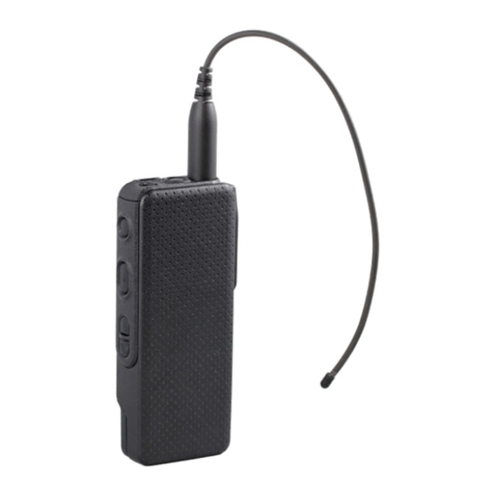
Introduction: Radio Description Radio Description The ASTRO APX 3000 radio provides improved voice quality across more coverage area. The digital process, called embedded signaling, intermixes system signaling information with digital voice, resulting in improved system reliability and the capability of supporting a multitude of advanced features. -
Page 31: Chapter 2 Basic Maintenance
General Maintenance In order to avoid operating outside the limits set by the FCC, align the ASTRO APX 3000 radio’s reference oscillator every time the radio is taken apart, or once per year, whichever comes first. (See Reference Oscillator Alignment). - Page 32 Never touch the equalization vent. Ensure that no oily substances come in contact with this vent. • The APX 3000 radio is designed to be submerged to a maximum depth of 1 meter, with a maximum submersion time of 30 minutes. Exceeding either maximum limit may result in damage to the radio.
-
Page 33: Chapter 3 Basic Theory Of Operation
Chapter 3 Basic Theory of Operation This chapter discusses the basic operational theory of the ASTRO APX 3000 radio, which is a wideband, synthesized radio available in the UHF1 (380–470 MHz), UHF2 (450–520 MHz), VHF (136–174 MHz) and 764–870 MHz frequency bands. All ASTRO APX3000 radios are capable of both analog operation (12.5 kHz or 25 kHz bandwidths), ASTRO mode (digital) operation (12.5 kHz... -
Page 34: Analog Mode Of Operation
Basic Theory of Operation: Analog Mode of Operation Analog Mode of Operation This section provides an overview of the analog mode receive and transmit theory of operation. 3.2.1 Receiving The RF signal is received at the antenna and is routed through the Harmonic Filter, followed by the Antenna Switch and finally the 15dB Step Attenuator IC. -
Page 35: Figure 3-4. Receiver Block Diagram (Vhf)
Basic Theory of Operation: Analog Mode of Operation Antenna 15 dB Step Switch Attenuator IF Filter ABACUS III Dec. ΣΔ ADC Filter Rx LO DIG_CTRL_ATTH 18Mhz Abacus III To GPS Diplexer Figure 3-4. Receiver Block Diagram (VHF) Antenna 15 dB Step Switch Attenuator IF Filter... - Page 36 Basic Theory of Operation: Analog Mode of Operation 3.2.1.2 UHF1 Front-End From the 15 dB Step Attenuator, a UHF1 signal is routed to the first pre-selector filter followed by an LNA and a second pre-selector filter. Both filters are discrete and tunable designs and are used to band limit the incoming energy and suppress known spurious responses such as Image and the ½...
-
Page 37: Figure 3-7. Transmitter (Uhf1/Uhf2) Block Diagram
Basic Theory of Operation: Analog Mode of Operation 3.2.2 Transmitting When the radio is transmitting, microphone audio is digitized and then processed by the DSP and sent to the Trident IC (see Figure 3-7, Figure 3-8 Figure 3-9) via the SSI interface. The Trident IC processes the SSI data for application to the voltage controlled oscillator as a modulation signal. -
Page 38: Figure 3-9. Transmitter (700/800 Mhz) Block Diagram
Basic Theory of Operation: Analog Mode of Operation Log Amp Power Detector Digital RF Attenuator Antenna Switch TX Buffer Amp Directional Harmonic TX Driver Amplifier Transmitter Final Coupler LP Filter FET 7/800 Mhz Antenna Connector TO RX Reverse Power Loop Filter Detection TX VCO Trident IC... -
Page 39: Digital (Astro) Mode Of Operation
Basic Theory of Operation: Digital (ASTRO) Mode of Operation Digital (ASTRO) Mode of Operation In the ASTRO (digital) mode of operation, the transmitted or received signal is limited to a discrete set of frequency deviation levels. The receiver handles an ASTRO-mode signal identically to an analog-mode signal, up to the point where the DSP decodes the received data. - Page 40 Basic Theory of Operation: Controller Section The ARM controller core of the OMAP processor handles the power up sequence of all devices, including firmware upgrades, and all operating system tasks that are associated with FLASH and SDRAM memories and user interface communication. The FLASH memory (64 MB) is required to store the firmware, tuning, and Codeplug settings, which upon initialization get read and stored into SDRAM (32MB) for execution.
-
Page 41: Figure 3-11. Gps/Bluetooth/Accelerometer Block Diagram
Basic Theory of Operation: Controller Section Main Board GPS_Shutdown // 1 GPS/RF Antenna OMAP 1710 UART (GPS Tx/Rx) // 2 SSI (BT Audio) // 4 GPS SAW GPS/RF filters & Diplexer Misc Control // 7 USB // 2 BT Antenna // 38 128MB ATMEL AVR32... - Page 42 3-10 Basic Theory of Operation: Controller Section Notes...
-
Page 43: Chapter 4 Recommended Test Equipment And Service Aids
The “Characteristics” column is included so that equivalent equipment may be substituted; however, when no information is provided in this column, the specific Motorola model listed is either a unique item or no substitution is recommended. -
Page 44: Service Aids
These kits and/or parts are available from the Radio Products and Solutions Organization offices listed in Replacement Parts Ordering. While all of these items are available from Motorola, most are standard shop equipment items, and any equivalent item capable of the same performance may be substituted for the item listed. -
Page 45: Chapter 5 Performance Checks
Chapter 5 Performance Checks This chapter covers performance checks used to ensure that the ASTRO APX 3000 radio meets published specifications. The recommended test equipment listed in the previous section approaches the accuracy of the manufacturing equipment, with a few exceptions. Accuracy of the test equipment must be maintained in compliance with the manufacturer’s recommended calibration... -
Page 46: Table 5-1. Initial Equipment Control Settings
Performance Checks: Test Equipment Setup Initial equipment control settings should be as indicated in Table 5-1 and should be the same for all performance checks and alignment procedures, except as noted. Table 5-1. Initial Equipment Control Settings System Analyzer Test Set Power Supply Monitor Mode: Standard* Spkr/Load: Speaker... -
Page 47: Display Radio Test Mode
Performance Checks: Display Radio Test Mode Display Radio Test Mode This section provides instructions for performing tests in display radio test mode (DRSM or debugging fixture required). NOTE: The radio needs to be attach to a Display RSM to enable the display capability. 5.2.1 Access the Test Mode To enter the display radio test mode:... -
Page 48: Rf Test Mode
5.2.2 RF Test Mode When the ASTRO APX 3000 radio is operating in its normal environment, the radio's microcomputer controls the RF channel selection, transmitter key-up, and receiver muting, according to the customer codeplug configuration. However, when the unit is on the bench for testing, alignment, or repair, it must be removed from its normal environment using a special routine, called RF TEST MODE. -
Page 49: Table 5-3. Test Frequencies (Mhz)
Performance Checks: Display Radio Test Mode Table 5-3. Test Frequencies (MHz) UHF1 UHF2 700–800 MHz Test Channel 380.075 380.025 450.075 450.025 136.075 136.025 764.0625 764.0125 390.075 390.025 460.075 460.025 142.075 142.125 769.0625 769.0125 400.075 400.025 471.075 471.025 154.275 154.225 775.9375 775.9875 411.075 411.025... -
Page 50: Receiver Performance Checks
Performance Checks: Receiver Performance Checks 6. Press Up Arrow Button; “99/1” appears; release, “99/0” appears. 7. Press the Down Arrow Button; “100/1” appears; release, “100/0” appears. Receiver Performance Checks The following tables outline the performance checks for the receiver. Table 5-5. Receiver Performance Checks Test Name System Analyzer Radio... -
Page 51: Table 5-6. Receiver Tests For Astro Conventional Channels
Performance Checks: Receiver Performance Checks Table 5-6. Receiver Tests for ASTRO Conventional Channels* Test Name System Analyzer Radio Test Set Comments Bit Error rate Mode: Proj 25 Std Radio Tuner PTT to OFF BER < 0.01% (BER) Floor RF Control: Gen Software (Bit Error (center) (Use test setup shown in... -
Page 52: Transmitter Performance Checks
Performance Checks: Transmitter Performance Checks Transmitter Performance Checks The following tables outline the performance checks for the transmitter. Table 5-7. Transmitter Performance Checks – APX 3000 Test Name System Analyzer Radio Test Set Comments Reference RF Control: Monitor TEST MODE CSQ PTT to continuous UHF1: ±2 ppm... -
Page 53: Table 5-8. Transmitter Tests For Astro Conventional Channels - Apx 3000
Performance Checks: Transmitter Performance Checks Table 5-8. Transmitter Tests for ASTRO Conventional Channels – APX 3000 Test Name System Analyzer Radio Test Set Comments RF Power Mode: Proj 25 Std Radio Tuner PTT to continuous UHF1: 1–5 Watt RF Control: Monitor Software not used. - Page 54 5-10 Performance Checks: Transmitter Performance Checks Notes...
-
Page 55: Chapter 6 Radio Alignment Procedures
Chapter 6 Radio Alignment Procedures This chapter describes both receiver and transmitter radio alignment procedures. Test Setup A personal computer (PC) and tuner software are required to align the radio. Refer to the applicable manual for installation and setup procedures for the software. To perform the alignment procedures, the radio must be connected to the PC and to a universal test set. -
Page 56: Tuner Main Menu
Radio Alignment Procedures: Tuner Main Menu Tuner Main Menu › › › Select Tuner from the START menu by clicking Start Program Files Motorola › › ASTRO 25 Products ASTRO 25 Tuner. To read the radio, use the File Read Device menu or click on Figure 6-2 illustrates how the alignment screens are organized. -
Page 57: Figure 6-3. Typical Softpot Screen
Radio Alignment Procedures: Softpot Figure 6-3. Typical Softpot Screen Adjusting the softpot value sends information to the radio to increase (or decrease) the voltage in the corresponding circuit. For example, left-clicking the UP spin button in the New Softpot Value scroll box on the Reference Oscillator screen instructs the radio’s microcomputer to increase the voltage across a varactor in the reference oscillator, which increases the frequency. -
Page 58: Radio Information
Radio Alignment Procedures: Radio Information Radio Information Figure 6-4 shows a typical Radio Information screen. This screen is informational only and cannot be directly changed. Figure 6-4. Radio Information Screen Transmitter Alignments 6.5.1 Reference Oscillator Alignment Adjustment of the reference oscillator is critical for proper radio operation. Improper adjustment will result not only in poor operation, but also in a misaligned radio that will interfere with other users operating on adjacent channels. -
Page 59: Figure 6-5. Reference Oscillator Alignment Screen (Uhf1)
Radio Alignment Procedures: Transmitter Alignments This test can be done with either the R-2670 Communication Analyzer or the 8901_ Modulation Analyzer. • Initial setup using the R-2670 Communication Analyzer: - RF Control: MONITOR - B/W: WB - Freq: CPS frequency under test - Attenuation: 20dB - Mon RF in: RF I/O - Meter: RF Display... -
Page 60: Figure 6-6. Reference Oscillator Alignment Screen (Uhf2)
Radio Alignment Procedures: Transmitter Alignments Figure 6-6. Reference Oscillator Alignment Screen (UHF2) Figure 6-7. Reference Oscillator Alignment Screen (VHF) -
Page 61: Figure 6-8. Reference Oscillator Alignment Screen (700/800 Mhz)
Radio Alignment Procedures: Transmitter Alignments Figure 6-8. Reference Oscillator Alignment Screen (700/800 MHz) 1. Make sure the Communication Analyzer is in Manual mode. UHF1 • Set the base frequency to 469.925 MHz UHF2 • Set the base frequency to 519.975 MHz •... -
Page 62: Table 6-1. Reference Oscillator Alignment
Radio Alignment Procedures: Transmitter Alignments Table 6-1. Reference Oscillator Alignment Band Target UHF1 ±50 Hz UHF2 ±50 Hz ±50 Hz 700/800 MHz ±100 Hz 3. Left-click the Program All button on the screen to dekey the radio and save the tuned values. 4. -
Page 63: Figure 6-10. Transmit Power Characterization Points Alignment Screen (Uhf2)
Radio Alignment Procedures: Transmitter Alignments Figure 6-10. Transmit Power Characterization Points Alignment Screen (UHF2) Figure 6-11. Transmit Power Characterization Points Alignment Screen (VHF) -
Page 64: Figure 6-12. Transmit Power Characterization Points Alignment Screen (700/800Mhz)
6-10 Radio Alignment Procedures: Transmitter Alignments Figure 6-12. Transmit Power Characterization Points Alignment Screen (700/800MHz) - Page 65 Radio Alignment Procedures: Transmitter Alignments 6-11 6.5.3 Power Characterization Tuning Tuning of the radio is done through Power Characterization tuning screen. IMPORTANT: Power Characterization Tuning Points must be tuned before tuning Power Characterization Tuning. NOTE: a The longer the RF cable, the more the attenuation of the power reading. b Use a standard 50 Ohm cable c Remember to set the Communication Analyzer to baseband power.
-
Page 66: Figure 6-13. Transmit Power Characterization Alignment Screen (Uhf1)
6-12 Radio Alignment Procedures: Transmitter Alignments Figure 6-13. Transmit Power Characterization Alignment Screen (UHF1) Figure 6-14. Transmit Power Characterization Alignment Screen (UHF2) -
Page 67: Figure 6-15. Transmit Power Characterization Alignment Screen (Vhf)
Radio Alignment Procedures: Transmitter Alignments 6-13 Figure 6-15. Transmit Power Characterization Alignment Screen (VHF) Figure 6-16. Transmit Power Characterization Alignment Screen (700/800 MHz) -
Page 68: Figure 6-17. Pa Saturation Referencing Alignment Screen (Uhf1)
6-14 Radio Alignment Procedures: Transmitter Alignments 6.5.4 PA Saturation Reference Tuning Tuning is done through PA Saturation Referencing screen. 1. Select the PA Saturation Reference alignment screen. The screen indicates the transmit frequencies to be used. See Figure 6-17, Figure 6-18, Figure 6-19 Figure... -
Page 69: Figure 6-18. Pa Saturation Referencing Alignment Screen (Uhf2)
Radio Alignment Procedures: Transmitter Alignments 6-15 Figure 6-18. PA Saturation Referencing Alignment Screen (UHF2) Figure 6-19. PA Saturation Referencing Alignment Screen (VHF) -
Page 70: Figure 6-20. Pa Saturation Referencing Alignment Screen (700/800 Mhz)
6-16 Radio Alignment Procedures: Transmitter Alignments Figure 6-20. PA Saturation Referencing Alignment Screen (700/800 MHz) 6.5.5 Transmit Deviation Balance Alignment This alignment procedure balances the modulation contributions of the low- and high-frequency portions of a baseband signal. Proper alignment is critical to the operation of signalling schemes that have very low frequency components (for example, DPL) and could result in distorted waveforms if improperly adjusted. - Page 71 Radio Alignment Procedures: Transmitter Alignments 6-17 - In the “RF Control” section of the R-2670, move the cursor to the “B/W” setting and select “WIDE +/- 100 kHz” on the soft key menu. - Place the R-2670 cursor in the “Display” zone. Select “AC VOLTS” on the soft key menu. Move the cursor to the “Range”...
-
Page 72: Figure 6-21. Transmit Deviation Balance Alignment Screen (Uhf1)
6-18 Radio Alignment Procedures: Transmitter Alignments Figure 6-21. Transmit Deviation Balance Alignment Screen (UHF1) Figure 6-22. Transmit Deviation Balance Alignment Screen (UHF2) -
Page 73: Figure 6-23. Transmit Deviation Balance Alignment Screen (Vhf)
Radio Alignment Procedures: Transmitter Alignments 6-19 Figure 6-23. Transmit Deviation Balance Alignment Screen (VHF) Figure 6-24. Transmit Deviation Balance Alignment Screen (700/800 MHz) -
Page 74: Front End Filter Alignment
6-20 Radio Alignment Procedures: Front End Filter Alignment Front End Filter Alignment Notes This procedure should only be attempted by qualified service technicians. The alignment procedure adjusts the front end receiver bandpass filters for the best receiver sensitivity and selectivity. This procedure should be performed for all test frequencies to allow for proper software interpolation of frequencies between the test frequencies in the band (see Figure 6-25... -
Page 75: Performance Testing
Radio Alignment Procedures: Performance Testing 6-21 2. Click on the slider or the "New Softpot Value" text box to select which frequency to tune. 3. Apply RF test signal input with no modulation at -90 dBm on the Test Signal Frequency displayed at the top of the screen. - Page 76 Selecting External will route the same signal to the radio's accessory connector audio output. Selecting Mute will disable the audio output. NOTE: There will be no audio option available for APX 3000 when performing a Bit Error Rate Test. • BER Integration Time: BER Integration Time carries with Test Pattern Type.
-
Page 77: Figure 6-27. Bit Error Rate Screen (Uhf1)
Radio Alignment Procedures: Performance Testing 6-23 Figure 6-27. Bit Error Rate Screen (UHF1) Figure 6-28. Bit Error Rate Screen (UHF2) -
Page 78: Figure 6-29. Bit Error Rate Screen (Vhf)
6-24 Radio Alignment Procedures: Performance Testing Figure 6-29. Bit Error Rate Screen (VHF) Figure 6-30. Bit Error Rate Screen (700/800 MHz) -
Page 79: Figure 6-31. Transmitter Test Pattern Screen (Uhf1)
Radio Alignment Procedures: Performance Testing 6-25 6.7.2 Transmitter Test Pattern The Transmitter Test Pattern test is used to transmit specific test patterns at a desired frequency so that the user can perform tests on the radio’s transmitter (see Figure 6-31, Figure 6-32, Figure 6-33... -
Page 80: Figure 6-32. Transmitter Test Pattern Screen (Uhf2)
6-26 Radio Alignment Procedures: Performance Testing Figure 6-32. Transmitter Test Pattern Screen (UHF2) Figure 6-33. Transmitter Test Pattern Screen (VHF) -
Page 81: Figure 6-34. Transmitter Test Pattern Screen (700/800 Mhz)
Radio Alignment Procedures: Performance Testing 6-27 Figure 6-34. Transmitter Test Pattern Screen (700/800 MHz) - Page 82 6-28 Radio Alignment Procedures: Performance Testing Notes...
-
Page 83: Chapter 7 Encryption
4. When the key is loaded successfully, you will hear: • On single-key radios – a short tone. • On multikey radios – an alternating tone. The secure kits for APX 3000 are identified by the following kit numbers: Table 7-1. Kit Numbers for Secure-Enabled Boards Kit Number... -
Page 84: Multikey Feature
Select an Encryption Key Encryption key is strapped to personality/channel programmable via CPS. Erase an Encryption Key APX 3000 only supports this feature for erasing an encryption key. - Page 85 Encryption: Erase an Encryption Key 7.4.1 All Keys Erased To erase all encryption keys at one time: With the radio on, press and hold the Top Side button and, while holding this button down, press the Top button. NOTE: DO NOT press the Top button before pressing the Top Side button unless you are in an emergency situation.
- Page 86 Encryption: Erase an Encryption Key Notes...
-
Page 87: Chapter 8 Disassembly/Reassembly Procedures
This chapter provides detailed procedures for disassembling/reassembling and ensuring submergibility of the APX 3000 radios. When performing these procedures, refer to Exploded Views and Parts Lists and the diagrams that accompany the text. Items in parentheses ( ) throughout this chapter refer to item numbers in the exploded view diagrams and their associated parts lists. -
Page 88: Table 8-1. Apx 3000 Partial Exploded View Parts List
Disassembly/Reassembly Procedures: APX 3000 Exploded View (Main Subassemblies) Figure 8-1. APX 3000 Partial Exploded View Table 8-1. APX 3000 Partial Exploded View Parts List Item Description Exploded View and Parts List Letter Figure 10-1 Front Kit Assembly Refer to Figure 10-2... -
Page 89: Required Tools And Supplies
Disassembly/Reassembly Procedures: Required Tools and Supplies Required Tools and Supplies Table 8-2. Required Tools and Supplies Motorola Supplier Part Tools Supplier Remarks Part Number Number Chassis Opener PMLN6208_ Horizon – To remove chassis from housing. Land Bit, Torx T6 –... -
Page 90: Radio Disassembly
Disassembly/Reassembly Procedures: Radio Disassembly Radio Disassembly This section contains instructions for disassembling the radio's main subassemblies. Prepare the radio for disassembly: • Turn off the radio by switching the On/Off switch. • Remove the Accessory-Connector cover (5†), the antenna, the battery, the Bottom Label (46†††) and any other accessory connected to the radio. -
Page 91: Figure 8-3. Removing The Antenna
If the radio is programmed for volatile-key retention, encryption keys will be retained for approximately 30 seconds after battery removal. NOTE: The Motorola-approved battery shipped with the APX 3000 radio is uncharged. Prior to using a new battery, charge it per the recommended procedure for the battery. -
Page 92: Figure 8-4. Lifting Up The Latch
Disassembly/Reassembly Procedures: Radio Disassembly 1. With the radio turned off, lift up the latch located at the bottom of the battery. Lift up Battery Latch Figure 8-4. Lifting up the latch 2. While lifting the latch, remove the battery by sliding it out as shown. Slide down Figure 8-5. -
Page 93: Figure 8-6. Disengage The Chassis
Disassembly/Reassembly Procedures: Radio Disassembly 8.4.4 Removal of the Back Kit Assembly ( This section contains instructions for disassembling the radio. 8.4.4.1 Removal of the Chassis (33†††) 1. With the Battery removed, disengage the Chassis (33†††) using the Chassis Opener as shown in Figure 8-6. -
Page 94: Figure 8-8. Remove The Chassis Screws
Disassembly/Reassembly Procedures: Radio Disassembly 8.4.4.2 Removal of the Secondary Shield Assembly (26†††*) 1. Remove the chassis screws (26†††*) as shown in Figure 8-8. Chassis Screws Secondary Shield Figure 8-8. Remove the chassis screws 2. With the chassis screws removed, lift the Secondary Shield Assembly (26†††*) out from the Chassis (33†††) as shown in Figure 8-9. -
Page 95: Figure 8-10. Remove The Main O-Ring At The Antenna Holder
Disassembly/Reassembly Procedures: Radio Disassembly 8.4.4.3 Removal of the Main Board(29††) 1. Remove the Main O-Ring (28†††*) and NFC Flex connector at the antenna holder as shown Figure 8-10. Antenna Holder Figure 8-10. Remove the Main O-Ring at the antenna holder 2. -
Page 96: Serviceable Components Of The Main Sub-Assemblies
8-10 Disassembly/Reassembly Procedures: Serviceable Components of the Main Sub-Assemblies 8.4.4.4 Removal of Battery Seal (40†††*) 1. Remove the battery seal at battery contact (40†††*) as shown in Figure 8-12. Battery Seal Contact Figure 8-12. Remove Battery Seal Serviceable Components of the Main Sub-Assemblies 8.5.1 Servicing Main Board Assembly Plastic Collar... -
Page 97: Figure 8-14. Serviceable Components - Chassis Assembly
Disassembly/Reassembly Procedures: Serviceable Components of the Main Sub-Assemblies 8-11 8.5.1.2 Servicing Thermal Pad: 1. Complete steps from Section 8.4.4.1. through Section 8.4.4.3. 2. Carefully peel off the pad. 3. Ensure there is no debris or residue left on the amplifier’s surface. 4. -
Page 98: Table 8-4. Serviceable Components
8-12 Disassembly/Reassembly Procedures: Serviceable Components of the Main Sub-Assemblies Table 8-4. Serviceable Components Item No. Description Label Shroud Screw, Shroud Bluetooth Pairing Indication Label Shroud Lightpipe, LEDs Assy, Flex, NFC Chassis Main Seal Label, Chassis Left Label, Chassis Right Seal, Vacuum Port Label, Gore Port Label, FM Approved Logo (Bottom) Label, Bottom Blank... - Page 99 Disassembly/Reassembly Procedures: Serviceable Components of the Main Sub-Assemblies 8-13 6. Apply slight pressure for approximately 30 seconds to activate the adhesive. Seal, Vacuum Port should always be replaced when back kit assembly is removed. 8.5.2.3 Servicing Battery Contact Seal: 1. Complete steps from Section 8.4.4.1.
-
Page 100: Figure 8-15. Serviceable Components - Main Housing
8-14 Disassembly/Reassembly Procedures: Serviceable Components of the Main Sub-Assemblies 8.5.3 Servicing Main Housing ( 1. Remove top control Bracket and Rotary Switch spring (which is attached to the top control bracket) at the same time. 2. Remove top control Assy Flex. Top control bracket Rotary switch spring Top control assy flex... -
Page 101: Radio Reassembly
Disassembly/Reassembly Procedures: Radio Reassembly 8-15 Radio Reassembly This section contains instructions for reassembling the radio. 8.6.1 Reassemble the Battery Seal(40†††*) 1. Assemble the battery seal (40†††*) as shown in Figure 8-16. Battery Seal Contact Figure 8-16. Assemble the Battery Seal 2. -
Page 102: Figure 8-18. Assemble The Rf Board
8-16 Disassembly/Reassembly Procedures: Radio Reassembly 8.6.2 Reassemble the Main Board (29††) 1. Place the Main Board into the Chassis (33+++) as shown in Figure 8-18. Main Board Figure 8-18. Assemble the RF Board NOTE: Ensure that the Battery Contact Seal (40†††*) does not pinch and the tabs of the Main O-Ring are held in place when assembling the Main Board into the Chassis. -
Page 103: Figure 8-20. Torque In The Chassis Screws
Disassembly/Reassembly Procedures: Radio Reassembly 8-17 2. Torque all seven Chassis Screws (25†††) with a Torx IP6 Bit and a Torque Driver to 3.0 in-lbf in the sequence as shown in Figure 8-20. Chassis Screws Secondary Shield Figure 8-20. Torque in the Chassis Screws. 8.6.4 Reassemble the Main Subassemblies (A and B) 1. -
Page 104: Figure 8-22. Assemble Back Kit And Front Kit Together
8-18 Disassembly/Reassembly Procedures: Radio Reassembly 3. With the Chassis assembly fully slided in, press down the bottom part of the Chassis to lock the two subassemblies (A and B) together as shown in Figure 8-22. Back Kit Assembly Front Kit Assembly Figure 8-22. -
Page 105: Figure 8-24. Securing The Cover
Disassembly/Reassembly Procedures: Radio Reassembly 8-19 2. Hand tighten the thumb screw clockwise until secured. NOTE: Do not overtighten the screw. The screw should be snugged and does not allow the cover to move. Thumb Screw with Hex Head Socket Figure 8-24. Securing the Cover 8.6.6 Reassemble the Antenna 1. -
Page 106: Figure 8-26. Assemble The Seal, Vacuum Port
8-20 Disassembly/Reassembly Procedures: Radio Reassembly 8.6.7 Reassemble the Seal, Vacuum Port (45†††*), Label Gore Port (43†††) and Bottom Label (45†††) 1. Adhere and gently press the Seal, Vacuum Port (43†††) on the chassis’ recess as shown in Figure 8-26. Vacuum port seal Figure 8-26. -
Page 107: Figure 8-28. Assemble The Bottom Label
Disassembly/Reassembly Procedures: Radio Reassembly 8-21 3. Adhere the Bottom Label (46†††) on the recess at the bottom of the Front Housing as shown Figure 8-28. Bottom label Figure 8-28. Assemble the Bottom Label 8.6.8 Reassemble the Battery 1. With the radio turned off, slide up the battery into the radio’s frame until the bottom latch clicks into place as shown in Figure 8-29. -
Page 108: Ensuring Radio Submergibility
This section discusses radio submergibility concerns, tests, and disassembly and reassembly of ASTRO APX 3000 radios. 8.7.1 Standards ASTRO APX 3000 radio models meet the stringent requirements of IP67, which require the radio to maintain watertight integrity when immersed in one (1) metre water for 30 minutes. 8.7.2 Servicing APX 3000 radios shipped from the Motorola factory have passed vacuum testing and should not be disassembled. - Page 109 Disassembly/Reassembly Procedures: Ensuring Radio Submergibility 8-23 8.7.5 Reassembly Do not reassemble the radio without first performing the following preliminary inspection procedure. To reassemble the radio: 1. Inspect the Main O-Ring on the Chassis (33†††) for any damage or foreign material. 2.
-
Page 110: Figure 8-30. Attaching Vacuum Test Fixture
8-24 Disassembly/Reassembly Procedures: Ensuring Radio Submergibility 8.7.6.2 Test Procedure Figure 8-30. Attaching Vacuum Test Fixture 1. Place the radio in the vacuum test fixture. Ensure the radio position is lay perfectly into the mold. 2. Pull the knob on the Vacuum Pump to create vacuum. The vacuum test pressure should be 6.6 inHg. - Page 111 Disassembly/Reassembly Procedures: Ensuring Radio Submergibility 8-25 8.7.7 Immersibility Test Immersibility testing the radio is necessary only if the radio has failed the vacuum test. Do not perform the test until the vacuum test has been completed. Immersibility test involves creating sealed condition inside the radio, submerging the radio in water, and observing the radio for a stream of bubbles (leak).
-
Page 112: Troubleshooting Leak Areas
8-26 Disassembly/Reassembly Procedures: Ensuring Radio Submergibility 8.7.8 Troubleshooting Leak Areas Before repairing any leak, first read all of the steps within the applicable section. This will help to eliminate unnecessary disassembly and reassembly of a radio with multiple leaks. NOTE: All disassembly and reassembly methods can be found in Section 8.4. -
Page 113: Chapter 9 Basic Troubleshooting
Level one and two troubleshooting will support only radio alignment, programming, battery replacement and circuit board replacement. Component-level service information can be found in the “ASTRO APX 3000 Portable Radios Detailed Service Manual,” Motorola publication number 68012007045. -
Page 114: Operational Error Codes
Basic Troubleshooting: Operational Error Codes Table 9-1. Power-Up Error Code Displays (Continued) Error Description Corrective Action Code 02/90 General DSP Hardware Failure (DSP startup message not Turn the radio off, then on received correctly) 09/10 Secure Hardware Error Turn the radio off, then on 09/90 Secure Hardware Fatal Error Turn the radio off, then on... -
Page 115: Transmitter Troubleshooting
Basic Troubleshooting: Transmitter Troubleshooting Table 9-3. Receiver Troubleshooting Chart (Continued) Correction or Test Symptom Possible Cause (Measurements at Room Temperature) Audio Distorted or Not Loud Synthesizer Not On Check synthesizer frequency by measuring the Enough Frequency transmitter frequency; realign if off by more than ±1000 Hz RF Sensitivity Poor 1. -
Page 116: Encryption Troubleshooting
Basic Troubleshooting: Encryption Troubleshooting Encryption Troubleshooting Table 9-5 lists the possible causes of, and corrections for, encryption problems. Table 9-5. Encryption Troubleshooting Chart Symptom Possible Cause Corrective Action No “KEYLOADING” on External Display 1. Defective Keyload Cable Send radio to depot When Keyloading Cable is Attached to the 2. -
Page 117: Chapter 10 Exploded Views And Parts Lists
Chapter 10 Exploded Views and Parts Lists This chapter contains exploded views and associated parts lists for the ASTRO APX 3000 digital portable radios. The following table lists the exploded views for the radio in different configurations: Table 10-1. APX 3000 Exploded Views and Controller Kit... -
Page 118: 10.1 Apx 3000 Front Kit Exploded View
10-2 Exploded Views and Parts Lists: APX 3000 Front Kit Exploded View 10.1 APX 3000 Front Kit Exploded View Figure 10-1. APX 3000 Front Kit Exploded View... -
Page 119: 10.2 Apx 3000 Front Kit Exploded View Parts List
Exploded Views and Parts Lists: APX 3000 Front Kit Exploded View Parts List 10-3 10.2 APX 3000 Front Kit Exploded View Parts List Item Motorola Part Description Number † 13012038001 Bezel. Side † 75012180001 Side Control, Silicon † 11012095001 Mylar, PEN/PET, Adhesive, Seal †... -
Page 120: 10.3 Apx 3000 Back Kit Exploded View
10-4 Exploded Views and Parts Lists: APX 3000 Back Kit Exploded View 10.3 APX 3000 Back Kit Exploded View Figure 10-2. APX 3000 Back Kit Exploded View... -
Page 121: 10.4 Apx 3000 Back Kit Exploded View Parts List
Exploded Views and Parts Lists: APX 3000 Back Kit Exploded View Parts List 10-5 10.4 APX 3000 Back Kit Exploded View Parts List Item Motorola Part Description Number †††* 0386104Z04 Screw, Chassis †††* 26012242001 Shield, Secondary †††* 43012045001 Collar, Plastic †††*... - Page 122 10-6 Exploded Views and Parts Lists: APX 3000 Back Kit Exploded View Parts List Notes...
-
Page 123: Appendix A Accessories
Appendix A Accessories Motorola provides the following approved optional accessories to improve the productivity of the APX 3000 portable radio. For a complete list of Motorola-approved antennas, batteries, and other accessories, visit the following web site: http://www.motorolasolutions.com/APX... - Page 124 Accessories Notes...
-
Page 125: Appendix B Replacement Parts Ordering
Read the Transceiver Board note, and include the proper information with your order. Motorola Online Motorola Online users can access our online catalog at http://www.motorolasolutions.com To register for online access, please call 1-800-422-4210 (for U.S. and Canada Service Centers only). -
Page 126: Telephone Orders
Sec 3: B-2 Replacement Parts Ordering: Telephone Orders Telephone Orders Radio Products and Solutions Organization* (United States and Canada) 7:00 AM to 7:00 PM (Central Standard Time) Monday through Friday (Chicago, U.S.A.) 1-800-422-4210 1-847-538-8023 (United States and Canada) U.S. Federal Government Markets Division (USFGMD) 1-877-873-4668 8:30 AM to 5:00 PM (Eastern Standard Time) Fax Orders... -
Page 127: Glossary
A device that converts analog signals into digital data. See also DAC. converter ASTRO 25 trunking Motorola standard for wireless digital trunked communications. ASTRO conventional Motorola standard for wireless analog or digital conventional communications. automatic level A circuit in the transmit RF path that controls RF power amplifier output, control provides leveling over frequency and voltage, and protects against high VSWR. - Page 128 Glossary-2 Glossary Term Definition carrier squelch Feature that responds to the presence of an RF carrier by opening or unmuting (turning on) a receiver's audio circuit. A squelch circuit silences the radio when no signal is being received so that the user does not have to listen to “noise.”...
- Page 129 Glossary Glossary-3 Term Definition digital Refers to data that is stored or transmitted as a sequence of discrete symbols from a finite set; most commonly this means binary data represented using electronic or electromagnetic signals. See also analog. digital-to-analog Conversion of a digital signal to a voltage that is proportional to the input conversion value.
- Page 130 FLASHcodes are only applicable for radios which are upgradeable through the FLASHport process. FLASHport A Motorola term that describes the ability of a radio to change memory. Every FLASHport radio contains a FLASHport EEPROM memory chip that can be software written and rewritten to, again and again.
- Page 131 Master Out Slave In SPI data line from the MCU to a peripheral. See microcontroller unit. Motorola Digital Communications. menu entry A software-activated feature shown at the bottom of the display. Selection of a feature is controlled by the programming of the buttons on the side of the radio.
- Page 132 Data transmitted on the control channel from the central controller to the word subscriber unit. over-molded pad- A Motorola custom IC package, distinguished by the presence of solder array carrier balls on the bottom pads. over-the-air rekeying Allows the dispatcher to remotely reprogram the encryption keys in the radio.
- Page 133 Glossary Glossary-7 Term Definition personality A set of unique features specific to a radio. phase-locked loop A circuit in which an oscillator is kept in phase with a reference, usually after passing through a frequency divider. See private-line tone squelch. See phase-locked loop.
- Page 134 Glossary-8 Glossary Term Definition receiver Electronic device that amplifies RF signals. A receiver separates the audio signal from the RF carrier, amplifies it, and converts it back to the original sound waves. registers Short-term data-storage circuits within the microcontroller unit or programmable logic IC.
- Page 135 Glossary Glossary-9 Term Definition Serial A full-duplex (receiver/transmitter) asynchronous serial interface. Communication Interface Input Line SCI IN See Serial Communication Interface Input Line. Serial Peripheral How the microcontroller communicates to modules and ICs through the Interface CLOCK and DATA lines. signal An electrically transmitted electromagnetic wave.
- Page 136 Glossary-10 Glossary Term Definition tactical/non-revert The user will talk on the channel that was selected before the radio entered the emergency state. TalkAround Bypassing a repeater and talking directly to another unit for local unit-to- unit communications. talkgroup An organization or group of radio users who communicate with each other using the same communications path.
- Page 137 Glossary Glossary-11 Term Definition See voltage-controlled oscillator. vector sum excited A voice-encoding technique used in ASTRO digital voice. linear predictive coding VOCON See vocoder/controller. vocoder An electronic device for synthesizing speech by implementing a compression algorithm particular to voice. See also voice encoder. vocoder/controller A PC board that contains an ASTRO radio’s microcontroller, DSP, memory, audio and power functions, and interface support circuitry.
- Page 138 Glossary-12 Glossary Notes...
- Page 139 Index-1 expansion board assembly removing 9, 10 Index housing assembly reassembling 15, 16 introduction 1 Numerics speaker grill assembly 700-800 MHz removing 7 model chart xxiv speaker module radio specifications xxvii, xxviii removing 8 universal connector cover alignment, tuner attaching 18 bit error rate test 21 removing 4 introduction 1...
- Page 140 Index-2 numbering system xix ASTRO mode 7 UHF1 xxi, xxii, xxiii reference oscillator alignment 4 model numbering system, radio xix replacement parts, ordering 1 multikey rf coax cable conventional 2 servicing 12, 13 trunked 2 RF exposure compliance information iii RF test mode dual-display version 4 notations...
- Page 141 Index-3 trademark information iii transmit deviation balance alignment 16 transmitter ASTRO conventional channel tests 9 performance checks 8 test pattern 25 troubleshooting 3 transmitting analog mode 5 ASTRO mode 7 troubleshooting encryption problems 4 introduction 1 operational error codes 2 power-up error codes 1 receiver problem chart 2 transmitter problem chart 3...
- Page 142 Index-4 Notes...
- Page 144 MOTOROLA, MOTO, MOTOROLA SOLUTIONS and the Stylized M logo are trademarks or registered trademarks of Motorola Trademark Holdings, LLC and are used under license. All other trademarks are the property of their respective owners. © 2013 Motorola Solutions, Inc. All rights reserved.