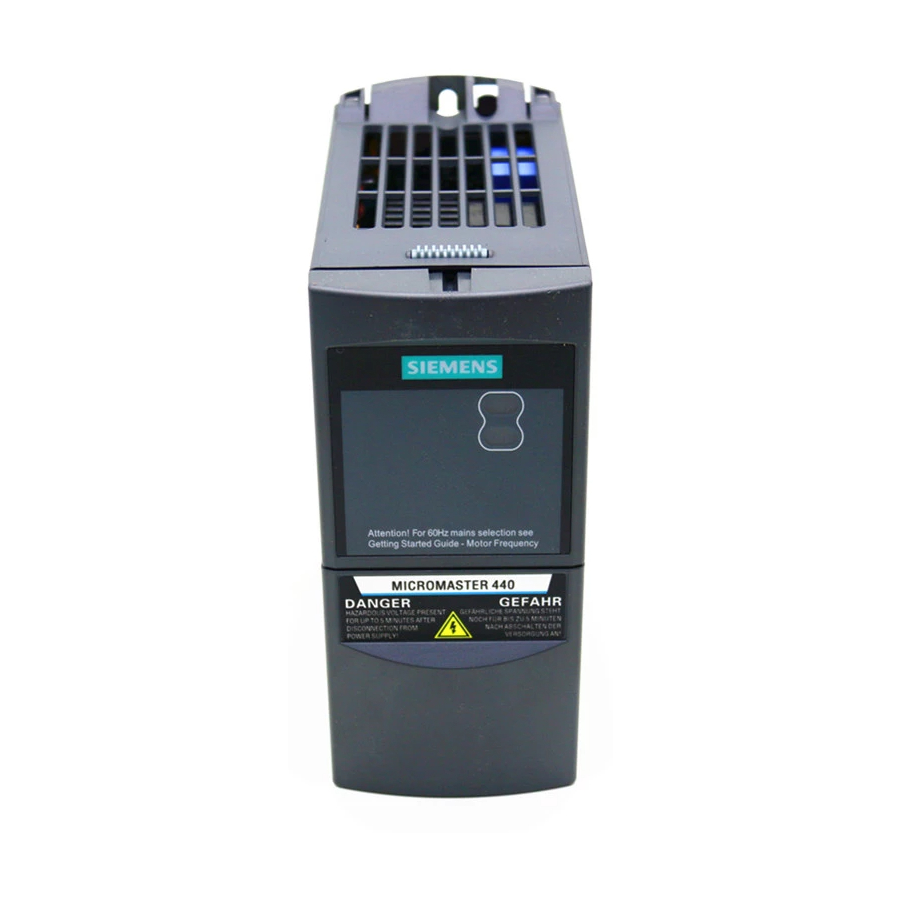
Siemens MICROMASTER 440 Quick Start Manual
Hide thumbs
Also See for MICROMASTER 440:
- Parameter manual (329 pages) ,
- Operating instructions manual (312 pages) ,
- Getting started manual (20 pages)
Table of Contents
Advertisement
Advertisement
Table of Contents

Related Manuals for Siemens MICROMASTER 440


Summary of Contents for Siemens MICROMASTER 440
- Page 1 Issue 08/03 MICROMASTER 440 Quick Start Guide 6SE6400-5GA00-0BP0...
- Page 2 Part Number 6SE6400-5AD00-1AP0 Start-Up Guide Gives basic information necessary for mechanical installation, quick commissioning, Analog and Digital I/O settings, common applications with examples and troubleshooting – specific for the MICROMASTER 440 Part Number 6SE6400-5GA00-0BP0 Operating Instructions Gives information about features of the...
-
Page 3: Issue
Issue 08/03 Mechanical Installation Wiring Guidelines / Electrical Installation MICROMASTER 440 50Hz / 60Hz Switch 1/6 HP – 350 HP Control Wiring Information Quick Start Guide Parameter Settings User Documentation Troubleshooting Valid for Issue 05/04 Inverter Type Software Version MICROMASTER 440 2.0x... - Page 4 We welcome suggestions for utility model or design are reserved. improvement. © Siemens AG 2001, 2002, 2003. All Rights Reserved. Siemens handbooks are printed on chlorine-free paper that has been produced from managed sustainable MICROMASTER® is a registered trademark of Siemens forests.
- Page 5 Earth voltage. This connection is normally used to ground the motor. Use for intended purpose only The equipment may be used only for the application stated in the manual and only in conjunction with devices and components recommended and authorized by Siemens. MICROMASTER 440 Quick Start Guide 6SE6400-5GA00-0BP0...
- Page 6 Please read the information carefully, since it is provided for your personal safety and will also help prolong the service life of your MICROMASTER 440 Inverter and the equipment you connect to it. General WARNING •...
- Page 7 The connection of power, motor and control cables to the inverter must be carried out as shown in Figure 2-6 Motor and Power Connections on page 21, to prevent inductive and capacitive interference from affecting the correct functioning of the inverter. MICROMASTER 440 Quick Start Guide 6SE6400-5GA00-0BP0...
- Page 8 This equipment must not be used as an ‘emergency stop mechanism’ (see EN 60204, 9.2.5.4) Repair WARNING • Repairs on equipment may only be carried out by Siemens Service Centers. • Any defective parts or components must be replaced using parts contained in the relevant spare parts list. •...
-
Page 9: Table Of Contents
Setting up Inputs and Outputs, ................53 Other Commonly Used Features ............... 60 Troubleshooting ..................... 62 Troubleshooting Using the Status Display Panel (SDP) ........62 Faults and Alarms (Warnings) ................64 Where to Get Additional Technical Information ..........67 MICROMASTER 440 Quick Start Guide 6SE6400-5GA00-0BP0... - Page 10 Issue 08/03 Quick Start Guide MICROMASTER 440 6SE6400-5GA00-0BP0...
-
Page 11: Mechanical Installation
Issue 08/03 Mechanical Installation Drilling Patterns and Dimensions Frame Size A - Frame Size C Figure 1-1 Drilling Pattern & Dimensions Frame Size A - Frame Size C MICROMASTER 440 Quick Start Guide 6SE6400-5GA00-0BP0... - Page 12 Issue 08/03 Frame Size E – Frame Size F Figure 1-2 Drilling Pattern & Dimensions Frame Size E - Frame Size F Quick Start Guide MICROMASTER 440 6SE6400-5GA00-0BP0...
- Page 13 Issue 08/03 Frame Size FX – Frame Size GX Figure 1-3 Drilling Pattern & Dimensions Frame Size FX - Frame Size GX MICROMASTER 440 Quick Start Guide 6SE6400-5GA00-0BP0...
-
Page 14: Environment, Heat Loss And Air Flow
233 (6.60) 6SE6440-2UC33-0FA1 14” (350mm) 14” (350mm) 318 (9.00) 6SE6440-2UC33-7FA1 1100 14” (350mm) 14” (350mm) 318 (9.00) 6SE6440-2UC34-5FA1 1350 14” (350mm) 14” (350mm) 318 (9.00) Figure 1-4 Heat Loss, Clearances & Air Flow (230V) Quick Start Guide MICROMASTER 440 6SE6400-5GA00-0BP0... - Page 15 6SE6440-2UE34-5FA1 1350 14” (350mm) 14” (350mm) 318 (9.00) 6SE6440-2UE35-5FA1 1650 14” (350mm) 14” (350mm) 318 (9.00) 6SE6440-2UE37-5FA1 2250 14” (350mm) 14” (350mm) 318 (9.00) Figure 1-5 Heat Loss, Clearances & Air Flow (460V, 575V) MICROMASTER 440 Quick Start Guide 6SE6400-5GA00-0BP0...
- Page 16 Issue 08/03 Quick Start Guide MICROMASTER 440 6SE6400-5GA00-0BP0...
-
Page 17: Wiring Guidelines / Electrical Installation
Frame Sizes A to Frame Size F Frame Size A Frame Sizes B & C Frame Sizes D & E Frame Size F Figure 2-1 Power Terminal Layouts Frame Size A to Frame Size F MICROMASTER 440 Quick Start Guide 6SE6400-5GA00-0BP0... - Page 18 Bottom adjustment rail Bottom retaining screw Fan screws Shield connection control leads Fan fuses Transformer adaption Motor cable Phase U2/T1, V2/T2, W2/T3 Motor cable PE Shield connection Figure 2-2 Layout of Frame Size FX Quick Start Guide MICROMASTER 440 6SE6400-5GA00-0BP0...
- Page 19 Bottom adjustment rail Bottom retaining screw Fan screws Shield connection control leads Fan fuses Transformer adaption Motor cable Phase U2/T1, V2/T2, W2/T3 Motor cable PE Shield connection Figure 2-3 Power Terminals Frame Size GX MICROMASTER 440 Quick Start Guide 6SE6400-5GA00-0BP0...
-
Page 20: Adaptation Of Fan Voltage (Only Frame Size Fx And Gx)
6SY7000-0AC48 GX (200-300 HP 4 A / 600 V / Ferraz Gould Shawmut ATDR4, 600 V or slow-acting comparable fuse Table 2-5 Replacement Fuses for Frame Size FX, Frame Size GX Fans Quick Start Guide MICROMASTER 440 6SE6400-5GA00-0BP0... -
Page 21: Motor And Power Connections
Issue 08/03 Motor and Power Connections MICROMASTER 440 drives and options should always be connected up in accordance with the diagram below: Single Phase (Frame Sizes A to C) Optional Optional Optional line choke Filter MICROMASTER Motor Contactor Fuse L/L1... -
Page 22: Recommended Power Supplies For 3Ph Connection
3ph Drive 3ph Drive Remove Y Capacitor Remove Y Capacitor Figure 2-7 - Recommended Power Supplies NOTE For ALL other line configurations an isolation transformer should be used with a grounded Wye secondary. Quick Start Guide MICROMASTER 440 6SE6400-5GA00-0BP0... -
Page 23: Removal Of Y Capacitor
2.4). This arrangement is sometimes used in industrial installations because, in the event of an ground fault occurring, the equipment may continue to run. CAUTION Ungrounded does not mean there is no ground connection at all. All Siemens drives must always be grounded. This is important for safety reasons. MICROMASTER 440... -
Page 24: Wiring Diagrams For Motors
400 V 400 V Line 690 V Delta connection Star connection Delta connection Star connection Figure 2-9 IEC Motor Connections NOTE Refer to page 45 for information on reading the motor name plate data. Quick Start Guide MICROMASTER 440 6SE6400-5GA00-0BP0... -
Page 25: When To Use Line Reactors (Input Chokes)
300 feet Table 2-10 Cable lengths using Siemens Load Reactors For all other frame sizes, Siemens load reactors allow up to 600 feet with shielded cable or up to 900 feet with unshielded cable across the recommended voltage range. MICROMASTER 440... -
Page 26: Fuses, Circuit Breakers, Line Reactors, Output Reactors
6SE6440-2UC31-1DA1 6SE6400-3CC05-2DD0 6SE6400-3TC05-4DD0 6SE6440-2UC31-5DA1 6SE6400-3CC05-2DD0 6SE6400-3TC05-4DD0 6SE6440-2UC31-8EA1 6SE6400-3CC08-8EC0 6SE6400-3TC08-0ED0 6SE6440-2UC32-2EA1 6SE6400-3CC08-8EC0 6SE6400-3TC08-0ED0 6SE6440-2UC33-0FA1 FXD6 6SE6400-3CC11-7FD0 6SE6400-3TC15-4FD0 6SE6440-2UC33-7FA1 FXD6 6SE6400-3CC11-7FD0 6SE6400-3TC15-4FD0 6SE6440-2UC34-5FA1 FXD6 6SE6400-3CC11-7FD0 6SE6400-3TC15-4FD0 Table 2-11 Fuses, Circuit Breakers and Reactors for MM440 230V Quick Start Guide MICROMASTER 440 6SE6400-5GA00-0BP0... - Page 27 6SE6400-3TC14-5FD0 6SE6440-2UD38-8FA1 JXD6 6SL3000-0CE32-3AA0 Consult Factory 6SE6440-2UD41-1FA1 JXD6 6SL3000-0CE32-8AA0 Consult Factory 6SE6440-2UD41-3GA1 JXD6 6SL3000-0CE33-3AA0 Consult Factory 6SE6440-2UD41-6GA1 6SL3000-0CE35-1AA0 Consult Factory 6SE6440-2UD42-0GA1 6SL3000-0CE35-1AA0 Consult Factory Table 2-12 Fuses, Circuit Breakers and Reactors for MM440 460V MICROMASTER 440 Quick Start Guide 6SE6400-5GA00-0BP0...
- Page 28 125% of actual motor Full Load Amps (FLA). Inverse time circuit breaker type per NEC minimum is 125% of actual motor FLA. The user should test the selected fuse or breaker in all possible applications of the drive. Quick Start Guide MICROMASTER 440 6SE6400-5GA00-0BP0...
-
Page 29: 2.10 Power Cable Dimensions
3ph 230V Input 6SE6440-2UC11-2AA1 6SE6440-2UC12-5AA1 6SE6440-2UC13-7AA1 6SE6440-2UC15-5AA1 6SE6440-2UC17-5AA1 6SE6440-2UC21-1BA1 6SE6440-2UC21-5BA1 6SE6440-2UC22-2BA1 6SE6440-2UC23-0CA1 6SE6440-2UC24-0CA1 6SE6440-2UC25-5CA1 7 ½ 6SE6440-2UC27-5DA1 6SE6440-2UC31-1DA1 6SE6440-2UC31-5DA1 6SE6440-2UC31-8EA1 6SE6440-2UC32-2EA1 6SE6440-2UC33-0FA1 300MCM 300MCM 6SE6440-2UC33-7FA1 300MCM 300MCM 6SE6440-2UC34-5FA1 300MCM 300MCM Table 2-14 Cable Dimensions 230V MICROMASTER 440 Quick Start Guide 6SE6400-5GA00-0BP0... - Page 30 350MCM or 2*4/0 350MCM or 2*4/0 350MCM or 2*4/0 6SE6440-2UD41-3GA1 2* 500MCM 2*750MCM 2* 500MCM 2*750MCM 6SE6440-2UD41-6GA1 2* 500MCM 2*750MCM 2* 500MCM 2*750MCM 6SE6440-2UD42-0GA1 2* 500MCM 2*750MCM 2* 500MCM 2*750MCM Table 2-15 Cable Dimensions 460V Quick Start Guide MICROMASTER 440 6SE6400-5GA00-0BP0...
- Page 31 Drive Part Number. 3ph 575V Input 6SE6440-2UE17-5CA1 6SE6440-2UE21-5CA1 6SE6440-2UE22-2CA1 6SE6440-2UE24-0CA1 6SE6440-2UE25-5CA1 7 ½ 6SE6440-2UE27-5CA1 6SE6440-2UE31-1CA1 6SE6440-2UE31-5DA1 6SE6440-2UE31-8DA1 6SE6440-2UE32-2DA1 6SE6440-2UE33-0EA1 6SE6440-2UE33-7EA1 6SE6440-2UE34-5FA1 300MCM 300MCM 6SE6440-2UE35-5FA1 300MCM 300MCM 6SE6440-2UE37-5FA1 300MCM 300MCM Table 2-16 Cable Dimensions 575V MICROMASTER 440 Quick Start Guide 6SE6400-5GA00-0BP0...
- Page 32 Issue 08/03 Quick Start Guide MICROMASTER 440 6SE6400-5GA00-0BP0...
-
Page 33: 50Hz / 60Hz Switch
The units of the power parameters are, depending on P0100, either interpreted as kW value or hp value. NOTE Switch DIP2(1) behind the I/O board has no function. DON’T FORGET THIS STEP See section 3.1 for instructions MICROMASTER 440 Quick Start Guide 6SE6400-5GA00-0BP0... -
Page 34: How To Remove I/O Card To Get At Switches
DIP2(1) has no function Figure 3-1 Removing the I/O board on Frame Size A to Frame Size C MM440 NOTE Example shown is Frame Size A; Frame Size B & Frame Size C are similar. Quick Start Guide MICROMASTER 440 6SE6400-5GA00-0BP0... - Page 35 Example shown is Frame Size D; Frame Size E & Frame Size F are similar. 3.1.3 Frame Size FX to Frame Size GX For Frame Size FX & Frame Size GX, locate the I/O board and follow the same procedure as for Frame Size A. MICROMASTER 440 Quick Start Guide 6SE6400-5GA00-0BP0...
- Page 36 Issue 08/03 Quick Start Guide MICROMASTER 440 6SE6400-5GA00-0BP0...
-
Page 37: Control Wiring
Issue 08/03 Control Wiring Control Block Diagram, 125 HP to 300 HP Figure 4-1 Control Wiring Block Diagram MICROMASTER 440 Quick Start Guide 6SE6400-5GA00-0BP0... -
Page 38: Control Wiring Examples
Setpoint via the AIN 1, (0-10V) RUN command via DIN 1, REVERSE command via DIN 2, RESET via DIN 3, Output frequency via AOUT 1, Fault messages via RL1, Warnings via RL2. ?4.7k Ω Quick Start Guide MICROMASTER 440 6SE6400-5GA00-0BP0... - Page 39 5.5 on page 42 OUT1 OUT1 OUT2 OUT2 These are the default settings as shown. No parameter changes are necessary other than quick commissioning. AIN1 AIN1 AIN2 AIN2 ≥ 4.7k Ω ≥ 4.7k Ω MICROMASTER 440 Quick Start Guide 6SE6400-5GA00-0BP0...
- Page 40 Normally Closed Push Button (Momentary Action) NOTE: STOP START This method works by creating a latch from a flip Normally Open Push Button flop. It is set from DIN1 and (Momentary Action) START reset from DIN2 Quick Start Guide MICROMASTER 440 6SE6400-5GA00-0BP0...
- Page 41 AIN2 P0704[0]=0 (disabled) P0704[1]=0(disabled) AUTO = P0704[2]=1 (Run/Stop) DIN4 – RUN/STOP P0810=722.0 (DIN1-Hand) P0811=722.2 (DIN3-Auto) AIN1 = Setpoint P1000[0]=2 (AIN1) P1000[1]=1 (BOP/MOP) P1000[2]=2 AIN1) 0 – 20mA or 4 – 20mA 3 Position Switch MICROMASTER 440 Quick Start Guide 6SE6400-5GA00-0BP0...
- Page 42 This example gives you 2 fixed frequencies in either direction. If both Fixed Frequencies are selected together then the sum of P1003 and P1004 will be the setpoint. This may be limited by FMAX/FMIN Quick Start Guide MICROMASTER 440 6SE6400-5GA00-0BP0...
-
Page 43: Setting Parameters
Setting Parameters 5.1 Introduction to Basic Operator Panel (BOP). There are several types of parameters that can be changed on a MICROMASTER 440. This procedure describes how to use the BOP to change parameters. There are also read-only parameters denoted by rXXXX for information/monitoring purposes. -
Page 44: 5.2 Factory Reset
In quick commissioning you set all of the basic parameters necessary to get your motor turning. The user must obtain all motor data information from the name plate on the motor before beginning this process. Here is some information about how to read the parameter data from the name plate: Quick Start Guide MICROMASTER 440 6SE6400-5GA00-0BP0... -
Page 45: Reading Motor Name Plates
Issue 08/03 Reading Motor Name Plates 5.4.1 NEMA Motor Figure 5-1 Reading NEMA Motor Name Plate 5.4.2 IEC motor. Figure 5-2 Reading IEC Motor Name Plate MICROMASTER 440 Quick Start Guide 6SE6400-5GA00-0BP0... -
Page 46: Level 3 Quick Commissioning
(50/60Hz) at this point, please power down your MICROMASTER and change the DIP2(2) switch according to section 3 before continuing. Failure to follow this procedure will result in complete loss of your motor parameters at the next power cycle. Quick Start Guide MICROMASTER 440 6SE6400-5GA00-0BP0... - Page 47 Plate If the setting is 0, the value is automatically calculated. NOTE You will not see this parameter on your BOP if P0100=1 This is NOT the service factor (cos ϕ value is always<1) MICROMASTER 440 Quick Start Guide 6SE6400-5GA00-0BP0...
- Page 48 P0335[0] Enter Motor Cooling Method* Self-cooled using shaft mounted fan attached to the motor Force-cooled: Using a separately powered cooling P0500[0] Enter Technological Application Constant Torque Pumps and Fans Simple Positioning NOTE See P0205 Quick Start Guide MICROMASTER 440 6SE6400-5GA00-0BP0...
- Page 49 P1082. If the ramp-up time is set too low, this may result in alarm A0501 (current limit active) or the drive tripping out with fault F0001 (overcurrent). MICROMASTER 440 Quick Start Guide 6SE6400-5GA00-0BP0...
- Page 50 (e.g. suspended loads for crane applications). Before the motor data identification run is started, the potentially hazardous load must be carefully secured (e.g. by lowering the load to the floor or by clamping the load using a motor holding brake). Quick Start Guide MICROMASTER 440 6SE6400-5GA00-0BP0...
- Page 51 (motor data identification active) is automatically reset and P3900 is re-displayed. 3. QUICK COMMISSIONING IS NOW FINISHED. NOTE If you are going to run in Vector mode or Sensorless Vector mode then refer to the Operating Instructions for further information. MICROMASTER 440 Quick Start Guide 6SE6400-5GA00-0BP0...
-
Page 52: Checking Direction Of Motor Rotation
Faults, warnings, monitoring functions 2100 to 2199 TECH PID controller, free blocks 2200 to 2399 and 2800 … 2890 Table 5-3 Parameter Locations Please refer to the Parameter List document for further information on these groupings. Quick Start Guide MICROMASTER 440 6SE6400-5GA00-0BP0... -
Page 53: Setting Up Inputs And Outputs
MICROMASTER 440 has 6 digital inputs which can be expanded to a total of 8 by using the 2 analog inputs. The digital inputs can be freely programmed to create a function. It is possible to directly assign a pre-designed function using parameters P0701 - P0708 or to build your own function using BICO technology. - Page 54 BICO parameterization. NOTE Only experienced users should use the BICO parameterization and for applications where the possibilities provided by P0701 – P0708 are no longer adequate. Quick Start Guide MICROMASTER 440 6SE6400-5GA00-0BP0...
- Page 55 3 Unipolar current input with monitoring (0 to 20 mA) 4 Bipolar voltage input (-10 V to +10 V) (only AIN1) ≥ 4.7k Ω ≥ 4.7k Ω Figure 5-8 DIP Switch And P0756 for Analog Voltage Input MICROMASTER 440 Quick Start Guide 6SE6400-5GA00-0BP0...
- Page 56 The bipolar voltage input is only possible with analog input 1 (AIN1). If additional settings are required for your specific application, then please refer to the Operating Instructions and the Parameter List supplied on the CD-ROM with you MM440 drive. Quick Start Guide MICROMASTER 440 6SE6400-5GA00-0BP0...
- Page 57 FP2100 (in parameter list) Table 5-10 Relay Output Specifications The MICROMASTER 440 has many status bits and threshold bits which might be useful in the application. You can connect any of the 3 relays to any of these functions. Invert Relay 0 ...
- Page 58 Parameter Values above refer to r0052 and r0053 values. A complete list of all of the connectable parameters may be taken from the parameter list (on the CD that was supplied with the MM440 drive). Quick Start Guide MICROMASTER 440 6SE6400-5GA00-0BP0...
- Page 59 P0777-P0781. You get the output on the AOUT terminals (0-20mA). If you want voltage instead of current, you can put a 500 Ohm resistor across the output and for a 0-10V output. MICROMASTER 440 Quick Start Guide 6SE6400-5GA00-0BP0...
-
Page 60: Other Commonly Used Features
DC link has completely collapsed) before the line supply returns. The automatic restart function P1210 is shown in the following diagram (refer to Table 5.1) as a function of external states / events. Quick Start Guide MICROMASTER 440 6SE6400-5GA00-0BP0... - Page 61 5.9.4 Sensorless Vector Control (SLVC) / Vector Control (VC) Refer to Operating Instructions for further details on using Vector Control or Sensorless Vector Control or to Technical Support Website (see page 67 for contact details) MICROMASTER 440 Quick Start Guide 6SE6400-5GA00-0BP0...
-
Page 62: Troubleshooting
Issue 08/03 Troubleshooting WARNING • Repairs on equipment may only be carried out by Siemens Service & Repair Centers – See page 67 for contact details. • Any defective parts or components must be replaced using parts contained in the relevant spare parts list. - Page 63 (>4V) the bit will be ON. This parameter should be used just to check that your connection is OK Figure 6-3 r0722 Display When Both AINs High. There are some other parameters that can also be used to troubleshoot your analog signals. MICROMASTER 440 Quick Start Guide 6SE6400-5GA00-0BP0...
-
Page 64: Faults And Alarms (Warnings)
Duty cycle too demanding – load needs to be reduced or larger drive should be used. • Motor too large for drive – load needs to be reduced or larger drive should be used. Quick Start Guide MICROMASTER 440 6SE6400-5GA00-0BP0... - Page 65 Fan must turn when inverter is running • Pulse frequency (P1800) must be set to default value • Ambient temperature could be higher than specified for the inverter • A0505 Inverter Overload Load duty cycle must lie within specified limits MICROMASTER 440 Quick Start Guide 6SE6400-5GA00-0BP0...
- Page 66 Inverter Warning wiring to motor. A0923 Jog Left and Jog Right • Both JOG right and JOG left (P1055/P1056) have been requested. Applied Warning This freezes the RFG output frequency at its current value. Quick Start Guide MICROMASTER 440 6SE6400-5GA00-0BP0...
-
Page 67: Where To Get Additional Technical Information
Should any questions or problems arise regarding this manual, please contact GPD-marketing@sea.siemens.com - please quote the Issue Number from the document and the page number/section that you have a question about. Alternatively you can fax us on 1-678-297-7259 MICROMASTER 440 Quick Start Guide 6SE6400-5GA00-0BP0... - Page 68 Issue 08/03 Figure 6-1 Quick Start Guide MICROMASTER 440 6SE6400-5GA00-0BP0...