Siemens 7sr220 Configuration Manual
Hide thumbs
Also See for 7sr220:
- Application manual (40 pages) ,
- Installation manual (24 pages) ,
- Manual (17 pages)
Table of Contents
Advertisement
Quick Links
7SR210
Non-Directional Relay
7SR220
Directional Relay
Configuration Guide
(Software Version 2435H85008R7a-7a) (7SR210)
(Software Version 2435H85009R7a-7a) (7SR220)
The copyright and other intellectual property rights in this document, and in any model or article produced from it
(and including any registered or unregistered design rights) are the property of Siemens Protection Devices
Limited. No part of this document shall be reproduced or modified or stored in another form, in any data retrieval
system, without the permission of Siemens Protection Devices Limited, nor shall any model or article be
reproduced from this document unless Siemens Protection Devices Limited consent.
While the information and guidance given in this document is believed to be correct, no liability shall be accepted
for any loss or damage caused by any error or omission, whether such error or omission is the result of
negligence or any other cause. Any and all such liability is disclaimed.
©2011 Siemens Protection Devices Limited
Advertisement
Table of Contents

Related Manuals for Siemens 7sr220


Summary of Contents for Siemens 7sr220
- Page 1 Limited. No part of this document shall be reproduced or modified or stored in another form, in any data retrieval system, without the permission of Siemens Protection Devices Limited, nor shall any model or article be reproduced from this document unless Siemens Protection Devices Limited consent.
-
Page 2: Document Release History
7SR210 & 7SR220 Configuration Guide Document Release History This document is issue 2011/05. 2011/05 First issue Page 2 of 14 ©2011 Siemens Protection Devices Limited... -
Page 3: Table Of Contents
7SR210 & 7SR220 Configuration Guide Contents Document Release History ............................2 Software Revision History..................Error! Bookmark not defined. Contents .................................. 3 Section 1: Introduction ............................. 5 1.1 Relay Menus And Display ........................5 1.2 Operation Guide............................7 1.2.1 User Interface Operation......................7 Section 1: Configuring the Relay Using Reydisp Evolution.................. - Page 4 7SR210 & 7SR220 Configuration Guide List of Figures Figure 1.1-1 Menu…………………………………………………………………………………………......4 Figure 1.1-2 Fascia Contrast Symbol…………………………………………………………….……… ......4 Figure 1.1-3 Relay Fascia…………………………………………………………….………...........5 Figure 1.2-1 Relay Identifier Screen…………………………………………………..………….……......…6 Figure 1.2-3 Menu Structure for 7SR21 relay……………………………………..…………….…… ......…7 Figure 1.2-4 Menu Structure for 7SR22 relay……………………………………………………...… ......…8 Figure 2.1-1 USB connection to a PC……………………………………………….……………….…...
-
Page 5: Section 1: Introduction
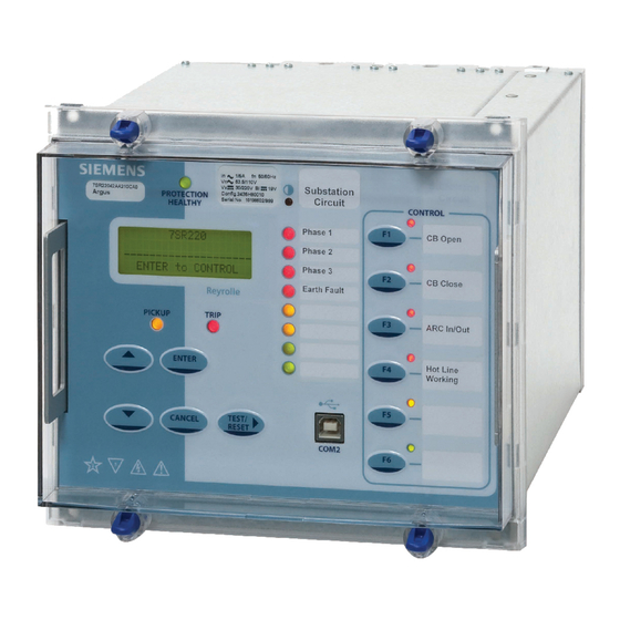
7SR210 & 7SR220 Configuration Guide Section 1: Introduction Relay Menus And Display All relay fascias contain the same access keys although the fascias may differ in appearance from model to model. The basic menu structure is also the same in all products and consists of four main menus, these being, Settings Mode - allows the user to view and (if allowed via the settings mode password) change settings in the relay. -
Page 6: Figure 1.1-3 Relay Fascia
7SR210 & 7SR220 Configuration Guide Figure 1.1-3 Relay Fascia (Please note fascia may differ from illustration) Page 6 of 14 ©2011 Siemens Protection Devices Limited... -
Page 7: Operation Guide
7SR210 & 7SR220 Configuration Guide Operation Guide 1.2.1 User Interface Operation The basic menu structure flow diagram is shown in Figure 1.2-2. This diagram shows the main modes of display: Settings Mode, Instrument Mode, Fault Data Mode and Control Mode. - Page 8 7SR210 & 7SR220 Configuration Guide 7SR22 ARGUS ____________________________ ENTER to CONTROL CONTROL MODE SETTINGS MODE INSTRUMENTS MODE FAULT DATA MODE CB TRAVELLING CLOSE I OPEN SYSTEM CONFIG FAVOURITE METERS NUMBER OF FAULTS AR : OUT OF SERVICE IN I OUT...
- Page 9 7SR210 & 7SR220 Configuration Guide 7SR22 ARGUS ____________________________ ENTER to CONTROL CONTROL MODE SETTINGS MODE INSTRUMENTS MODE FAULT DATA MODE CB TRAVELLING CLOSE I OPEN SYSTEM CONFIG FAVOURITE METERS NUMBER OF FAULTS AR : OUT OF SERVICE IN I OUT...
-
Page 10: Section 1: Configuring The Relay Using Reydisp Evolution
7SR210 & 7SR220 Configuration Guide Section 1: Configuring the Relay Using Reydisp Evolution To set the relay using the communication port the user will need the following:- PC with Reydisp Evolution Installed. (This can be download from our website www.siemens.com/energy found under the submenu ‘Software’). -
Page 11: Standard Rear Rs485 Connection
7SR210 & 7SR220 Configuration Guide 1.1.2 Standard rear RS485 connection Figure 2.1-2 Standard rear RS485 connection to a PC 1.1.3 Optional rear fibre optic connection Figure 2.1-3 Additional (Optional) rear fibre optic connection to a PC Sigma devices have a 25 pin female D connector with the following pin out. -
Page 12: Optional Rear Rs485 + Irig-B Connection
7SR210 & 7SR220 Configuration Guide 1.1.4 Optional rear RS485 + IRIG-B connection Figure 2.1-4 Additional (Optional) rear RS485 + IRIG-B connection to a PC 1.1.5 Optional rear RS232 + IRIG-B connection IRIG-B COM 3 USB or 9 pin male D connector... -
Page 13: Configuring Relay Data Communication
7SR210 & 7SR220 Configuration Guide 1.1.6 Configuring Relay Data Communication Using the keys on the relay fascia scroll down the settings menu’s into the ‘communications’ menu and change the settings for the communication port used on the relay. All of the below settings may not be available in all relay types. -
Page 14: Connecting To The Relay Via Reydisp Evolution
7SR210 & 7SR220 Configuration Guide 1.1.7 Connecting to the Relay via Reydisp Evolution When Reydisp Evolution software is running all available communication ports of the PC will automatically be detected. On the start page tool bar open up the sub-menu File > Connect.