Sign In
Upload
Manuals
Brands
York Manuals
Air Conditioner
YCAL0014E Series
York YCAL0014E Series Manuals
Manuals and User Guides for York YCAL0014E Series. We have
1
York YCAL0014E Series manual available for free PDF download: Installation Operation & Maintenance
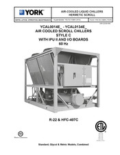
York YCAL0014E Series Installation Operation & Maintenance (212 pages)
AIR COOLED SCROLL CHILLERS STYLE C WITH IPU II AND I/O BOARDS 60 Hz
Brand:
York
| Category:
Air Conditioner
| Size: 11.94 MB
Table of Contents
Table of Contents
5
Fig. 1 - Refrigerant Flow Diagram
17
Section 1 - Installation
19
Installation Check List
19
Handling
19
Inspection
19
Location and Clearances
19
Foundation
20
Ground Level Locations
20
Rooftop Locations
20
Noise Sensitive Locations
20
Spring Isolators (Optional)
20
Compressor Mounting
20
Remote Cooler Option
20
Chilled Water Piping
20
General
20
Wiring
21
Field Wiring
21
Evaporator Pump Start Contacts
22
System Run Contacts
22
Alarm Status Contacts
22
Remote Start/Stop Contacts
22
Remote Emergency Cutoff
22
PWM Input
22
Load Limit Input
22
Flow Switch Input
22
Compressor Heaters
22
Single-Point Supply Connection - Terminal Block, Non-Fused Disconnect Switch or Circuit Breaker (0014 - 0080)
23
Fig. 2 - Single-Point Supply Connection - Terminal Block, Non-Fused Disconnect Switch or Circuit Breaker (0014 - 0080)
23
Multiple Point Power Supply Connection - Terminal Block (0040 - 0080)
24
Fig. 3 - Multiple Point Power Supply Connection - Terminal Block (0040 - 0080)
24
Multiple Point Power Supply Connection - Terminal Block, Non-Fused Disconnect Switches or Circuit Breakers (0090 - 0134)
25
Fig. 4 - Multiple Point Power Supply Connection - Terminal Block, Non-Fused Disconnect Switches or Circuit Breakers (0090 - 0134)
25
Single-Point Supply Connection - Terminal Block or Non-Fused Disconnect Switch to Individual System Circuit Breakers (0090 - 0134)
26
Fig. 5 - Optional Single-Point Power Wiring
26
Control Wiring
27
Fig. 6 - Control Wiring
27
Electrical Notes and Legend
28
Electrical Data
29
Table 1 - Micro Panel Power Supply
29
Single-Point Power Supply Connections - YCAL0014E_ - YCAL0034E
30
Table 2 - Single-Point Power Supply
30
Electrical Data - Dual Point Power Supply Connections - YCAL0040E_ - YCAL0080E
32
Table 3 - Dual Point Power Supply Connections
32
Electrical Data - Dual Point Power Supply Connections - YCAL0040E_ - YCAL0080E
33
Electrical Data - Single Point Power Supply Connections - YCAL0040E_ - YCAL0080E
34
Table 4 - Single Point Power Supply Connections
34
Electrical Data - Single Point Power Supply Connections - YCAL0040E_ - YCAL0080E
35
Electrical Data - Multiple Point Power Supply Connections - YCAL0090E_ - YCAL0134E
36
Table 5 - Multiple Point Power Supply Connections
36
Electrical Data - Multiple Point Power Supply Connections - YCAL0090E_ - YCAL0134E
37
Electrical Data - Single Point Power Supply Connections with Individual System Circuit Breakers - YCAL0090E_ - YCAL0134E
38
Table 6 - Single Point Power Supply Connections with Individual System Circuit Breakers
38
Electrical Data - Single Point Power Supply Connections with Individual System Circuit Breakers - YCAL0090E_ - YCAL0134E
39
Operational Limitations (English)
40
Voltage Limitations
40
Table 7 - Temperatures and Flows
40
Table 8 - Voltage Limitations
40
Table 9 - Cooler Pressure Drop Curves
41
Table 10 - Ethylene / Propylene Glycol Correction Factors
41
Operational Limitations (Metric)
42
Voltage Limitations
42
Table 11 - Temperatures and Flows
42
Table 12 - Voltage Limitations
42
Table 13 - Cooler Pressure Drop Curves
43
Table 14 - Ethylene / Propylene Glycolcorrection Factors
43
Physical Data (English) Ycal0014E_ - Ycal0134E
44
Table 15 - Physical Data (English)
44
Physical Data (Metric) Ycal0014E_ - Ycal0134E
46
Table 16 - Physical Data (Metric)
46
Dimensions and Clearances
48
Dimensions - YCAL0014-YCAL0020 (English)
48
Dimensions - YCAL0024-YCAL0034 (English)
50
Dimensions - YCAL0040-YCAL0060 (English)
52
Dimensions - YCAL0064-YCAL0080 (English)
54
Dimensions - YCAL0090-YCAL0094 (English)
56
Dimensions - YCAL0104 (English)
58
Dimensions - YCAL0114 - YCAL0134 (English)
60
Dimensions - YCAL0014-YCAL0020 (SI)
62
Dimensions - YCAL0024-YCAL0034 (SI)
64
Dimensions - YCAL0040-YCAL0060 (SI)
66
Dimensions -YCAL0064-YCAL0080 (SI)
68
Dimensions - YCAL0090-YCAL0094 (SI)
70
Dimensions - YCAL0104 (SI)
72
Dimensions - YCAL0114 - YCAL0134 (SI)
74
Equipment Pre-Startup and Startup Checklist
76
Pre-Startup
76
Startup
77
Table 17 - Setpoints Entry List
77
Checking Superheat and Subcooling
78
Leak Checking
79
Unit Operating Sequence
80
Section 2 - Unit Controls
81
Introduction
81
Ipu II and I/O Boards
81
Unit Switch
82
Display
82
Keypad
82
Battery Back-Up
82
Transformer
82
Single System Select and Programming # of Compressors
82
Status Key
83
General Status Messages
83
Fault Status Messages
85
Unit Warning
87
Status Key Messages
88
Table 18 - Status Key Messages
88
Display/Print Keys
89
Oper Data Key
89
Oper Data Quick Reference List
92
Table 19 - Operation Data
92
Print Key
93
Operating Data Printout
93
History Printout
94
History Displays
94
Software Version
97
Entry Keys
98
Up and down Arrow Keys
98
Enter/Adv Key
98
Setpoints Keys
99
Cooling Setpoints
99
Leaving Chilled Liquid Control
99
Return Chilled Liquid Control
100
Schedule/Advance Day Key
100
Table 20 - Cooling Setpoints, Programmable Limits and Defaults
101
Program Key
102
Table 21 - Program Key Limits and Defaults
105
Table 22 - Setpoints Quick Reference List
106
Unit Keys
107
Options Key
107
Clock
111
Table 23 - Unit Keys Programming Quick Reference List
112
Section 3 - Unit Operation
113
Capacity Control
113
Suction Pressure Limit Controls
113
Discharge Pressure Limit Controls
113
Leaving Chilled Liquid Control
113
Leaving Chilled Liquid Control Override to Reduce Cycling
114
Return Chilled Liquid Control
114
Fig. 7 - Setpoint Adjust
114
Fig. 8 - Leaving Water Temperature Control Example
114
Table 24 - Compressor Staging for Return Water Control
115
Table 25 - Return Chilled Liquid Control for 5 & 6 Compressors (7 & 8 Steps)
115
System Lead/Lag
116
Compressor Lead/Lag
116
Anti-Recycle Timer
116
Anti-Coincidence Timer
116
Table 26 - Return Chilled Liquid Control for 4 Compressors (6 Steps)
116
Evaporator Pump Control
117
Evaporator Heater Control
117
Pumpdown Control
117
Electronic Expansion Valve (Eev)
117
General
117
MOP Feature
117
Valve Preheat
117
Inputs
117
Outputs
118
Program
118
Safeties
118
Condenser Fan Control (Ycal0014 through Ycal0080 Chillers)
118
Condenser Fan Control (Ycal0090 through Ycal0134)
118
Low Ambient Condenser Fan Control (Ycal0014 through Ycal0080)
118
Condenser Fan Control
119
Ycal0014 - Ycal0080
119
Table 27 - Ycal0014 through Ycal0080 Condenser Fan Control Using Outdoor Ambient Temperature and Discharge Pressure
119
Fig. 9 - Ycal0014 through Ycal0080 Fan Location (Typical)
119
Table 28 - Ycal0014 through Ycal0080 Condenser Fan Control Using Discharge Pressure Only
120
Table 29 - Ycal0014 - Ycal0080 Low Ambient Condenser Fan Control
120
Ycal0090 - Ycal0104
121
Table 30 - Ycal0090 - Ycal0104 Condenser Fan Control
121
Fig. 10 - Ycal0090 through Ycal0104 Fan Location
121
Ycal0114 - Ycal0134
122
Table 31 - Ycal0114 - Ycal0134 Condenser Fan Control
122
Fig. 11 - Ycal0114 - Ycal0134 Fan Location
122
Load Limiting
123
Compressor Run Status
123
Alarm Status
123
Table 32 - Compressor Operation - Load Limiting
123
Ems-Pwm Remote Temperature Reset
124
Bas/Ems Temperature Reset Option
124
Fig. 12 - Field and Factory Electrical Connectionsoptional Remote Temperature Reset Board
125
Section 4 - Service and Troubleshooting
127
Clearing History Buffers
127
Software Version
127
Service Mode
127
Service Mode - Outputs
127
Service Mode - Chiller Configuration
127
Service Mode - Inputs
128
Control Inputs/Outputs
129
Table 33 - I/O Board Digital Inputs
129
Table 34 - I/O Board Analog Inputs
129
Table 35 - I/O Board Digital Outputs
129
Table 36 - I/O Board Analog Outputs
129
Fig. 13 - I/O Board Layout
130
Checking Inputs and Outputs
131
Table 37 - Outdoor Air Sensor Temperature/Voltage/ Resistance Correlation
131
Table 38 - Entering/Leaving Chilled Liquid Temp. Sensor, Cooler Inlet Temperature Sensor, and Suction Temperature Sensor: Temperature/Voltage/Resistance Correlation
132
Fig. 14 - I/O Board Relay Contact Architecture
134
Keypad
135
Table 39 - Keypad Pin Assignment Matrix
135
Assembly and Wiring
136
Fig. 15 - Printer to I/O Board Electrical Connections
136
Obtaining a Printout
136
Parts
136
Troubleshooting Charts
137
Table 40 - Troubleshooting
137
Section 5 - Maintenance
141
Important
141
Compressors
141
Oil Level Check
141
Oil Analysis
141
Condenser Fan Motors
141
Condenser Coils
141
Operating Parameters
141
On-Board Battery Back-Up
141
Overall Unit Inspection
141
Bacnet, Modbus and Yorktalk 2 Communications
142
Micro Panel Connections
143
Table 41 - Minimum, Maximum and Default Values
143
Table 42 - Values Required for Bas Communication
144
Table 43 - Real Time Error Numbers
144
Bacnet and Modbus Communications
145
Communications Data Map Notes
145
Table 44 - Bacnet and Modbus Communications Data Map
146
Yorktalk 2 Communications
149
Table 45 - Yorktalk 2 Communications Data Map
150
Section 6 - Wiring Diagrams
153
Ycal0014E_ - Ycal0030E
153
Fig. 16 - Elementary Diagram, Power Circuit - Ycal0014E_ - Ycal0030E
153
Fig. 17 - Elementary Diagram, Control Circuit - Ycal0014E_ - Ycal0030E
154
Fig. 18 - Connection Diagram, Middle Market - Ycal0014E_ - Ycal0030E
156
Fig. 19 - Elementary Diagram, Middle Market - Ycal0014E_ - Ycal0030E
158
Ycal0034E
159
Fig. 20 - Elementary Diagram, Power Circuit - Ycal0034E
159
Fig. 21 - Elementary Diagram, Middle Market - Ycal0034E
160
Fig. 22 - Connection Diagram, Middle Market - Ycal0034E
162
Fig. 23 - Elementary Diagram, Midlle Market - Ycal0034E
164
Ycal0040E_ - Ycal0060E
165
Fig. 24 - Elementary Diagram, Midlle Market - Ycal0040E_ - Ycal0060E
165
Fig. 25 - Elementary Diagram, Control Circuit - Ycal0040E_ - Ycal0060E
166
Fig. 26 - Elementary Diagram, Power Circuit - Ycal0040E_ - Ycal0060E
168
Fig. 27 - Connection Diagram, Middle Market - Ycal0040E_ - Ycal0060E
170
Ycal0064E_ - Ycal0080E
172
Fig. 28 - Elementary Diagram, Control Circuit - Ycal0064E_ - Ycal0080E
172
Fig. 29 - Elementary Diagram, Power Circuit - Ycal0064E_ - Ycal0080E
174
Fig. 30 - Connection Diagram, Middle Market - Ycal0064E_ - Ycal0080E
176
Fig. 31 - Elementary Diagram, Middle Market - Ycal0064E_ - Ycal0080E
178
Ycal0090E_ - Ycal0094E
179
Fig. 32 - Elementary Diagram, Middle Market - Ycal0090E_ - Ycal0094E
179
Fig. 33 - Elementary Diagram, Control Circuit - Ycal0090E_ - Ycal0094E
180
Fig. 34 - Elementary Diagram, Power Circuit - Ycal0090E_ - Ycal0094E
182
Fig. 35 - Connection Diagram, Middle Market High Performance - Ycal0090E_ - Ycal0094E
184
Ycal0104E
186
Fig. 36 - Elementary Diagram, Control Circuit - Ycal0104E
186
Fig. 37 - Elementary Diagram, Power Circuit - Ycal0104E
188
Fig. 38 - Connection Diagram, Middle Market High Performance - Ycal0104E
190
Fig. 39 - Elementary Diagram, Middle Market High Performance- Ycal0104E
192
Ycal0114E_ - Ycal0134E
193
Fig. 40 - Elementary Diagram, Middle Market High Performance - Ycal0114E_ - Ycal0134E
193
Fig. 41 - Elementary Diagram, Control Circuit - Ycal0114E_ - Ycal0134E
194
Fig. 42 - Elementary Diagram, Power Circuit - Ycal0114E_ - Ycal0134E
196
Fig. 43 - Connection Diagram, Middle Market High Performance - Ycal0114E_ - Ycal0134E
198
Section 7 - Isolator Data
201
Weight Distribution
201
Aluminum Fin Coils
201
Copper Fin Coils
202
Isolator Selections
203
Aluminum Fin Coils
203
Copper Fin Coils
205
Isolator Dimensions and Springs Cp-1 and Cp-2
207
Isolator Spring Identification Table
207
Fig. 44 - Type Cp 1
207
Fig. 45 - Type Cp 2
207
Seismic Isolator Dimensions
208
Fig. 46 - R Spring Seismic Isolator
208
Installation and Adjusting Installationstype Cp Mounting
209
Fig. 47 - Type Cp Mounting
209
Aeqm Spring-Flex Mounting
210
Installation and Adjustment Instructions
210
Fig. 48 - Aeqm Spring-Flex Mounting
210
Advertisement
Advertisement
Related Products
York YCAL0134E Series
YORK YCHD Series
York YC-9E
York YC120
York YCW-HW
York YCJD30S41 S3
York YCD18 THRU 60
York YCD36
York YCD24B21
York YCD42B21S
York Categories
Air Conditioner
Heat Pump
Chiller
Furnace
Air Handlers
More York Manuals
Login
Sign In
OR
Sign in with Facebook
Sign in with Google
Upload manual
Upload from disk
Upload from URL