Sign In
Upload
Manuals
Brands
Yamaha Manuals
Stereo Receiver
DSP-AX3900
Yamaha DSP-AX3900 Manuals
Manuals and User Guides for Yamaha DSP-AX3900. We have
1
Yamaha DSP-AX3900 manual available for free PDF download: Service Manual
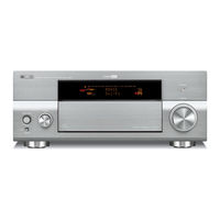
Yamaha DSP-AX3900 Service Manual (227 pages)
AV RECEIVER/AV AMPLIFIER
Brand:
Yamaha
| Category:
Stereo Receiver
| Size: 43.98 MB
Table of Contents
Table of Contents
1
Important Notice
1
Critical Components Information
2
Leakage Current Measurement (for 120V Models Only)
2
Warning: Chemical Content Notice
2
About Lead Free Solder
2
To Service Personnel
2
Warning: Lithium Batteries
3
Front Panels
3
Rear Panels
5
Remote Control Panels
9
Specifications
10
Dimensions
12
Select Menu
13
Set Menu Table/Manual Setup (GUI)
14
Internal View
16
Removal of Top Cover
17
Removal of Front Panel
17
Removal of Sub Chassis Unit
17
Disassembly Procedures
17
When Checking the Pcbs
18
Removal of A-Video PCB
19
Removal of D-Video PCB
19
When Checking the PCB
21
Removal of Rear Unit
22
Removal of Amp Unit
24
Updating Firmware
26
Confirmation of Firmware Version and Checksum
28
Rom Ver/Sum
28
Self-Diagnostic Function
30
Starting Self-Diagnostic Function in the Protection Cancel Mode
33
Display Provided When Self-Diagnostic Function Started
34
Canceling Self-Diagnostic Function
34
History of Protection Function
36
Display During Menu Operation
37
Operation Procedure of Main Menu and Sub-Menu
37
Functions in Self-Diagnostic Function Mode
38
Initial Settings Used to Start Self-Diagnostic Function
38
Input Change When Main Menu Is Selected
38
Details of Self-Diagnostic Function Menu
39
Analog Bypass
40
DSP Bypass
40
Speaker Set
42
HDMI Audio
42
Analog Switch Settings for each Sub-Menu
43
Multi CH Input
44
FL/OSD Check
45
Manual Test
46
Graphic (Display System)
47
FL Check
47
Checking FL Display Section
47
Zone Function Confirmation Item
48
R: Radio - Tuner and Satellite Broadcasting System
49
Sirius Test
51
HD Radio Test (U Model)
52
Universal - Special Terminal System (USB, Dock)
53
USB Check
54
Network Function System
56
Net Check
56
Ext Loopback Test
59
PHY Test
59
Communication and BUS Line Check Item, Etc.
60
Function PCB Check
60
DSP PCB Check
61
D-Video PCB Check
62
HDMI Information
63
EPROM Check
64
A-Video PCB Check
64
Digital Bypass
65
Rec Zone
65
Mute Check 1/2
66
OSD Character Pattern
66
Test Pattern
67
Video Info
67
HDMI Loop-Back Test
68
D-Video PCB Route Check
68
HDMI to Hdmi_Out1
70
CVBS to da and Hdmi_Out1
70
CVBS to da and Hdmi_Out1 with DDR
71
Y/C to da and Hdmi_Out1
71
Component_480P to da and Hdmi_Out1
72
Component_720P to Hdmi_Out1
72
YGV to da and Hdmi_Out1
73
Power Supply System
74
System Monitor
74
LMTCNT (Limiter Control Value)
75
AMPPOW (Amp. Power Control)
75
OUTLVL (Power Limiter Output Level)
75
TM1/TM2 (Temperature Detection)
75
AMPRELAY (Amp. Power Relay Control)
76
Model
76
Destination
76
Panel Key (K0/K1)
77
Protection Hist.
78
System Setting Confirmation Item
79
Firm Update
79
Tool Update
79
Factory Preset
80
Set Info
82
Soft Sw
82
Confirmation of Idling Current of Amp Unit
83
Amp Adjustment / Display Data
83
Display Data
84
Pin Connection
84
Grid Assignment
84
Anode Connection
85
IC Data
86
Main Microprocessor PCB
90
Destination for AD Port / Model Distinction for AD Port
96
Rx-V3900
96
DSP-AX3900 (J Model)
96
Expansion of Serial Parameter
96
Ic105: Ytd-446Cz (D-Video P.C.b.)
97
Ic114: Mb87L8760 (D-Videop.C.b)
101
Audio Section Block Diagram
104
Block Diagrams
104
Video Section Block Diagram
105
D-Video Section Block Diagram
106
Power Section Block Diagram
107
Control Section Block Diagram
108
Pin Connection Diagrams
109
DSP PCB View
112
Printed Circuit Boards
112
Function PCB View
114
Operation PCB View
118
Main PCB View
122
Power PCB
126
A-Video PCB View
130
D-Video PCB View
132
FL PCB View
134
Connect PCB View
140
DCCNVT PCB View
142
DSP Schematic
145
Schematic Diagrams
145
Function Schematic
148
Operation Schematic
152
Main Schematic
153
Power Schematic
154
A-Video Schematic
155
D-Video Schematic
157
FL Schematic Diagram
167
Connect Schematic
169
DCCNVT Schematic
170
Electrical Component Parts
171
Replacement Parts List
171
PCB DSP Parts
172
PCB Function Parts
177
PCB Operation Parts
183
PCB Main Parts
185
PCB Power Parts
189
PCB A-Video Parts
192
PCB D-Video Parts
196
PCB FL Parts
203
PCB Connect Parts
205
PCB DCCNVT Parts
206
Carbon Resistors
207
Overall Assy Exploded View
208
Overall Assy Parts List
209
Front Panel and Sub Chassis Unit Exploded View and Parts List
211
Amp Unit Exploded View and Parts List
212
Remote Control Schematic Diagram
213
Keys Layout - Remote Control
215
RAV36 Schematic Diagram
216
Remote Control ID Setting
217
Wake on RS-232C Access
217
Speaker Impedance
217
Advanced Setup
217
Bi-Amplifier Mode
218
Tuner Frequency Step
218
Parameter Initialization
218
MAC Address Filter
218
TV Format
219
HDMI Monitor Check
219
Language
219
Firmware Update
219
Resetting the System
220
Advertisement
Advertisement
Related Products
Yamaha DSP-AX757SE
Yamaha DSP-AX2600
Yamaha DSP-AX3200
Yamaha DSP-AX340
Yamaha DSP-AX361
Yamaha dsp-ax3800
Yamaha DSP-AX620
Yamaha DSP-AX1/RX-V1
Yamaha DSP-AX2700
Yamaha DSP-AX559
Yamaha Categories
Motorcycle
Musical Instrument
Electronic Keyboard
Receiver
Amplifier
More Yamaha Manuals
Login
Sign In
OR
Sign in with Facebook
Sign in with Google
Upload manual
Upload from disk
Upload from URL