UTICA BOILERS MAHF-165 Manuals
Manuals and User Guides for UTICA BOILERS MAHF-165. We have 3 UTICA BOILERS MAHF-165 manuals available for free PDF download: Installation, Operation And Maintenance Manual, Manual
UTICA BOILERS MAHF-165 Manual (139 pages)
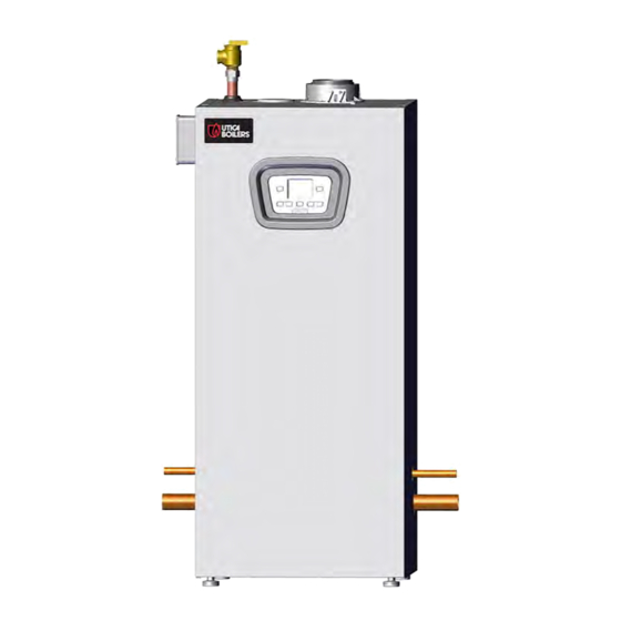
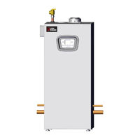
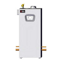
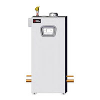
CONDENSING GAS FIRED BOILER
Brand: UTICA BOILERS
|
Category: Boiler
|
Size: 35.65 MB
Table of Contents
Advertisement
UTICA BOILERS MAHF-165 Installation, Operation And Maintenance Manual (139 pages)
CONDENSING GAS FIRED BOILER
Brand: UTICA BOILERS
|
Category: Boiler
|
Size: 12.63 MB
Table of Contents
UTICA BOILERS MAHF-165 Installation, Operation And Maintenance Manual (118 pages)
CONDENSING GAS FIRED BOILER
Brand: UTICA BOILERS
|
Category: Boiler
|
Size: 10.56 MB
Table of Contents
Advertisement