Sign In
Upload
Manuals
Brands
Trane Manuals
Chiller
CenTraVac CVHE
Trane CenTraVac CVHE Manuals
Manuals and User Guides for Trane CenTraVac CVHE. We have
2
Trane CenTraVac CVHE manuals available for free PDF download: Installation, Operation And Maintenance Manual, Assembly/Disassembly Manual
Trane CenTraVac CVHE Installation, Operation And Maintenance Manual (108 pages)
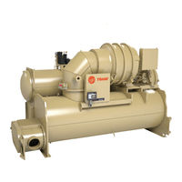
Water-cooled Chillers
Brand:
Trane
| Category:
Chiller
| Size: 5.31 MB
Table of Contents
Table of Contents
5
Unit Nameplate
8
Model Number Descriptions
9
Pre-Installation
10
ASHRAE Standard 15 Compliance
10
Unit Shipment
10
Installation Requirements and Contractor
10
Responsibilities
10
Storage Requirements
12
Unit Components
14
Unit Clearances and Weights
15
Recommended Unit Clearances
15
General Weights
16
Weights (Lb)
16
Weights (Kg)
20
Installation: Mechanical
25
Operating Environment
25
Foundation Requirements
25
Rigging
25
Standard Chiller Lift
25
Special Lift Requirements
27
Unit Isolation
27
Isolation Pads
27
Spring Isolators
27
Leveling the Unit
29
Installation: Water Piping
30
Overview
30
Water Treatment
30
Water Pressure Gauges
30
Valves - Drains and Vents
30
Strainers
31
Required Flow-Sensing Devices
31
Paddle Switches
31
Water Flow Detection Controller and Sensor
31
Evaporator and Condenser Water
33
Piping
33
Water Piping Connections
34
Waterbox Locations
35
Grooved Pipe Coupling
35
Flange-Connection Adapters
36
Victaulic Gasket Installation
36
Screw-Tightening Sequence for Water
37
Piping Connections
37
Flanges with 4, 8, or 12 Screws
38
Flanges with 16, 20, or 24 Screws
38
Flanges with more than
38
Screws
38
Evaporator Waterbox Covers
38
Pressure Testing Waterside Piping
39
Eddy Current Testing
39
Vent Piping
40
Refrigerant Vent Line
40
General Requirements
40
Purge Discharge
40
Vent Line Materials
40
Vent Line Sizing
40
Vent Line Installation
41
Vent Line Sizing Reference
44
Insulation
47
Unit Insulation Requirements
47
Insulation Thickness Requirements
47
Factory-Applied Insulation
47
Installation: Controls
49
Symbio™ 800
49
Adaptiview™ Display
49
Tracer TU
49
Control Panel
50
Installing the Tracer Adaptiview
52
Display
52
Adjusting the Tracer ® Adaptiview
52
Display Arm
53
Module Installation
54
Air-Fi
54
Wi-Fi
55
Electrical Requirements
56
Installation Requirements
56
Trane-Supplied Starter Wiring
57
Transformer Wire Sizing
58
Wiring
60
Power Supply Wiring
60
Three-Phase Power
60
Circuit Breakers and Fused
60
Disconnects
60
Power Factor Correction Capacitors
60
(Optional)
60
Interconnecting Wiring
61
Starter to Motor Wiring
62
Starters Only)
62
Ground Wire Terminal Lugs
62
Terminal Clamps
63
Wire Terminal Lugs
63
Bus Bars
63
Starter to Control Panel Wiring
64
10 To 13.8Kv Medium Voltage Motor
65
Motor Terminal Box
65
Motor Supply Wiring
65
Motor Terminals
66
Ground Wire Terminal Lug
66
System Control Circuit Wiring
67
Wiring)
67
Water Pump Interlock Circuits and Flow
68
Switch Input
68
Chilled Water Pump
68
Chilled Water Proof of Flow
68
Condenser Water Pump
68
Condenser Water Proof of Flow
68
Heat Recovery Proof of Flow
68
Temperature Sensor Circuits
69
CWR - Outdoor Option
69
Circuits
69
Starter Module Configuration
69
Schematic Wiring Drawings
69
Operating Principles
70
General Requirements
70
Cooling Cycle
70
CVHE and CVHG 3-Stage Compressor
70
CVHF 2-Stage Compressor
70
Oil and Refrigerant Pump
71
Compressor Lubrication System
71
Motor Cooling System
74
Tracer ® Adaptiview™ Display
74
Start-Up and Shutdown
75
Sequence of Operation
75
Software Operation Overview
75
Diagram
75
Start-Up Sequence of Operation-Wye
76
Delta
76
Power up
80
Ice Building Control
80
Free Cooling Cycle
82
Free Cooling (FRCL)
83
Hot Gas Bypass (HGBP)
83
Hot Water Control
83
Heat Recovery Cycle
84
Auxiliary Condensers
84
Control Panel Devices and Unit-Mounted
84
Devices
84
Unit Control Panel
84
User-Defined Language Support
84
Unit Start-Up and Shutdown
85
Procedures
85
Daily Unit Start-Up
85
Seasonal Unit Start-Up
86
Daily Unit Shutdown
86
Seasonal Unit Shutdown
86
Recommended Maintenance
87
Record Keeping Forms
87
Normal Operation
87
Recommended Compressor Oil
89
Change
89
Purge System
90
Leak Checking Based on Purge Pump
90
Out Time
90
Long Term Unit Storage
90
Refrigerant Charge
91
Leak Testing
91
Recommended System Maintenance
91
Condenser
92
Evaporator
92
Waterbox and Tubesheet Protective
92
Coatings
92
Sacrificial Anodes
92
Waterbox Removal and Installation
94
Discussion
94
Procedure
94
Reassembly
95
Torque Requirements and Waterbox
95
Weights
95
Connection Devices Information
96
Appendix A: Forms and Check Sheets
97
Unit Start-Up/Commissioning
97
Appendix B: Chiller Installation Completion and Request for Trane Service
98
Appendix C: Centravac™ Chiller Start-Up Tasks to be Performed by Trane
100
Appendix D: Centravac™ Chiller Annual
102
Inspection List
102
Appendix E: Centravac™ Chiller Operator
103
Log 2
103
Advertisement
Trane CenTraVac CVHE Assembly/Disassembly Manual (36 pages)
Brand:
Trane
| Category:
Chiller
| Size: 1.74 MB
Table of Contents
Warnings, Cautions, and Notices
2
Important Environmental Concerns
2
Important Responsible Refrigerant Practices
2
Revision History
3
Factory Warranty Information
3
General Information
4
Metric Conversions
5
Device Descriptions
5
Dimensions and Weights
6
Control Panel Removal
27
Heat Recovery
29
Free Cooling
30
Advertisement
Related Products
Trane CenTraVac CVHE Series
Trane CenTraVac CVHF Series
Trane CenTraVac CVHG Series
Trane CenTraVac CDHG
Trane CenTraVac CDHF
Trane CenTraVac CVHF
Trane CenTraVac CVHG
Trane CenTraVac CDHF Series
Trane CenTraVac CDHG Series
Trane CenTraVac CVHM
Trane Categories
Air Conditioner
Heat Pump
Chiller
Air Handlers
Furnace
More Trane Manuals
Login
Sign In
OR
Sign in with Facebook
Sign in with Google
Upload manual
Upload from disk
Upload from URL