Sign In
Upload
Manuals
Brands
Texas Instruments Manuals
Motherboard
mmWaveICBoost
Texas Instruments mmWaveICBoost Manuals
Manuals and User Guides for Texas Instruments mmWaveICBoost. We have
2
Texas Instruments mmWaveICBoost manuals available for free PDF download: User Manual
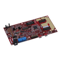
Texas Instruments mmWaveICBoost User Manual (82 pages)
With Antenna Module
Brand:
Texas Instruments
| Category:
Microcontrollers
| Size: 14.34 MB
Table of Contents
Table of Contents
1
Trademarks
4
1 Getting Started
5
Introduction
5
Key Features
5
What's Included
7
6 IWR6843AOPEVM (Deprecated)
7
2 Mmwaveicboost
9
Hardware
9
Figure 2-1. MMWAVEICBOOST Front View
9
Figure 2-2. MMWAVEICBOOST Rear View
9
Block Diagram and Features
10
Block Diagram
10
Figure 2-3. Block Diagram of MMWAVEICBOOST
10
Figure
10
Muxing Scheme for Multiple Sources
11
Figure 2-4. Muxing Scheme
11
Switch Settings
12
Figure 2-5. Front
14
Figure 2-6. Rear
14
Figure 2-7. Front
14
Using the MMWAVEICBOOST with the Starter Kit
15
PC Connection
15
Figure 2-8. Uninstalled Devices
15
Figure 2-9. COM Ports after the Driver Installation
16
Figure 2-10. Integration of MMWAVEICBOOST and Starter Kit
17
Figure 2-11. Mechanical Mounting of the PCB
17
Interfacing with the DCA1000EVM
18
Figure 2-12. IWR6843ISK-MMWAVEICBOOST-DCA1000EVM Test
18
Power Connections
19
Connectors
19
Figure 2-13. Power Connector
19
Figure 2-14. P3 Header
19
Figure 2-15. P7 Header
19
Figure 2-16. J27
19
Figure 2-17. TI Standard Launchpad
20
Figure 2-18. 60-Pin HD Connectors
21
Figure 2-19. 60-Pin HD Connector (DCA1000)
24
Figure 2-20. 60-Pin MIPI Connector
24
Figure 2-21. 14-Pin JTAG Connector
25
Jumpers, Switches and Leds
26
Figure 2-22. CAN Connectors
26
Figure 2-23. UMC Connector
26
Figure 2-24. SOP Jumpers
27
Figure 2-25. J13 Header
28
Table 2-12. 3.3-V Rail Options
28
Table 2-13. Miscellaneous Headers
28
Figure 2-26. SW1
29
Figure 2-27. SW2
29
Figure 2-28. S1 Switch
29
Table 2-14. Switches Information
29
Figure 2-29. DS1
30
Figure 2-30. DS2
30
Figure 2-31. Leds
30
Figure 2-32. D4 & D9
30
Table 2-15. Leds Information
30
3 Xwr6843Isk / IWR6843ISK-ODS REV C
31
Hardware
31
Figure 3-1. Xwr6843Isk Front View
31
Figure 3-2. Xwr6843Isk Rear View
32
Figure 3-3. PCB Antenna - Top
33
Figure 3-4. PCB Antenna - Bottom
33
Xwr6843Isk/Iwr6843Isk-ODS Block Diagram
34
PCB Storage and Handling Recommendations
34
Power Connections
34
Figure 3-5. Block Diagram of Xwr6843Isk/Iwr6843Isk-ODS
34
Interfaces
35
Figure 3-6. LED Location and Color
37
Table 3-1. List of Leds
37
Figure 3-7. CAN Connector Location and Label
38
Table 3-2. IWR6843ISK I2C Devices and Address
38
Xwr6843Isk Antenna
39
Figure 3-8. PCB Antennas
39
Figure 3-9. IWR6843ISK Antenna Placement MIMO Array
40
Figure 3-10. TX1 Antenna Radiation Pattern in
41
Figure 3-11. TX2 Antenna Radiation Pattern in Azimuth
41
Figure 3-12. TX3 Antenna Radiation Pattern in
41
Azimuth
41
Figure 3-13. TX1 Antenna Radiation Pattern in Elevation
41
Figure 3-14. TX2 Antenna Radiation Pattern in Elevation
41
Figure 3-15. TX3 Antenna Radiation Pattern in Elevation
41
Figure 3-16. IWR6843ISK-ODS PCB Antenna
42
IWR6843ISK-ODS Antenna
42
Modular Mode
44
Table 3-3. S1 Config Flashing and Functional Mode
45
DCA1000EVM Mode
46
MMWAVEICBOOST Mode
46
Table 3-4. S1 Config for DCA1000EVM Mode
46
Table 3-5. S1 Config for Mmwaveicboost Mode
47
4 Xwr6843Aopevm Rev F
48
Hardware
48
Block Diagram
49
PCB Storage and Handling Recommendations
50
Heat Sink and Temperature
50
Xwr6843Aopevm Antenna
53
Switch Settings
55
Table 4-1. Switches
55
Xwr6843Aopevm Muxing Scheme
56
Modular and MMWAVEICBOOST Mode
56
Table 4-2. Pin Mux Settings
56
Table 4-3. SOP Configuration
56
PC Connection
59
REACH Compliance
60
Table 4-4. REACH Information
60
5 IWR6843ISK / IWR6843ISK-ODS (Deprecated)
61
Hardware
61
IWR6843ISK/IWR6843ISK-ODS Block Diagram
64
PCB Storage and Handling Recommendations
64
Power Connections
64
Miscellaneous and Leds
65
Table 5-1. List of Leds
65
Table 5-2. IWR6843ISK I2C Devices and Address
65
IWR6843ISK Antenna
66
IWR6843ISK-ODS Antenna
68
IWR6843AOPEVM Antenna
72
Table 6-1. Switches
75
IWR6843AOPEVM Muxing Scheme
76
Modular and MMWAVEICBOOST Mode
76
Table 6-2. Pin Mux Settings I
76
Table 6-3. Pin Mux Settings II
76
REACH Compliance
80
7 TI E2E Community
81
Revision History
81
Advertisement
Texas Instruments mmWaveICBoost User Manual (80 pages)
Antenna Module
Brand:
Texas Instruments
| Category:
Motherboard
| Size: 17.44 MB
Table of Contents
Table of Contents
1
Getting Started
5
Introduction
5
Key Features
5
What's Included
7
Hardware
8
MMWAVEICBOOST Front View
8
MMWAVEICBOOST Rear View
8
Block Diagram and Features
9
Block Diagram of MMWAVEICBOOST
9
Muxing Scheme for Multiple Sources
10
Muxing Scheme
10
Switch Settings
11
Front
12
Rear
12
Mux Selection Images
12
Using the MMWAVEICBOOST with the Starter Kit
13
Uninstalled Devices
13
COM Ports after the Driver Installation
14
Integration of MMWAVEICBOOST and Starter Kit
15
Mechanical Mounting of the PCB
15
Interfacing with the DCA1000EVM
16
IWR6843ISK-MMWAVEICBOOST-DCA1000EVM Test Setup
16
Power Connections
17
Power Connector
17
P3 Header
17
P7 Header
17
J27 Header
17
Board Power
17
Connectors
18
TI Standard Launchpad
18
J6 Connector Pinout
18
60-Pin HD Connectors
19
J5 Connector Pinout
19
J4 Connector Pinout
20
J17 Connector Pinout
21
60-Pin HD Connector (DCA1000)
22
60-Pin MIPI Connector
22
14-Pin JTAG Connector
23
CAN Connectivity
23
Jumpers, Switches and Leds
24
CAN Connectors
24
UMC Connector
24
SOP Jumper Information
24
SOP Jumpers
25
I2C Jumper Settings
25
I2C Devices and Addresses
25
J13 Header
26
V Rail Options
26
Miscellaneous Headers
26
S1 Switch
27
Switches Information
27
Leds Information
28
Xwr6843Isk / IWR6843ISK-ODS REV C
29
Hardware
29
Xwr6843Isk Front View
29
Xwr6843Isk Rear View
30
PCB Antenna - Top
31
PCB Antenna - Bottom
31
Xwr6843Isk/Iwr6843Isk-ODS Block Diagram
32
PCB Storage and Handling Recommendations
32
Power Connections
32
Interfaces
33
List of Leds
35
Xwr6843Isk Antenna
37
IWR6843ISK I2C Devices and Address
37
IWR6843ISK-ODS Antenna
40
Modular Mode
42
S1 Config Flashing and Functional Mode
43
DCA1000EVM Mode
44
S1 Config for DCA1000EVM Mode
44
3.10 MMWAVEICBOOST Mode
45
S1 Config for Mmwaveicboost Mode
46
IWR6843AOPEVM Rev F
47
Hardware
47
Block Diagram
48
PCB Storage and Handling Recommendations
49
Heat Sink and Temperature
49
IWR6843AOPEVM Antenna
52
Switch Settings
54
Switches
54
IWR6843AOPEVM Muxing Scheme
55
Pin Mux Settings
55
SOP Configuration
55
Modular and MMWAVEICBOOST Mode
56
PC Connection
58
4.10 REACH Compliance
59
IWR6843ISK / IWR6843ISK-ODS (Deprecated)
59
Hardware
59
REACH Information
59
IWR6843ISK/IWR6843ISK-ODS Block Diagram
63
PCB Storage and Handling Recommendations
63
Power Connections
63
Miscellaneous and Leds
64
List of Leds
64
IWR6843ISK I2C Devices and Address
64
IWR6843ISK Antenna
65
IWR6843ISK-ODS Antenna
67
Measured Azimuthal Radiation Pattern for All Tx to Rx Pairs (All 12 Virtual Antenna Pairs Included)
67
Measured Elevation Radiation Pattern for All Tx to Rx Pairs (All 12 Virtual Antenna Pairs Included)
68
IWR6843AOPEVM (Deprecated)
69
Hardware
69
IWR6843AOPEVM Top View
69
Block Diagram
70
IWR6843AOPEVM Bottom View
70
Block Diagram of the IWR6843AOPEVM
70
PCB Storage and Handling Recommendations
71
IWR6843AOPEVM Antenna
71
AOP Antennas
71
Measured Azimuthal Radiation Pattern for All Tx to Rx Pairs (All 12 Virtual Antenna Pairs Included)
72
Measured Elevation Radiation Pattern for All Tx to Rx Pairs (All 12 Virtual Antenna Pairs Included)
72
Switch Settings
73
IWR6843AOPEVM Switches
73
Switches
73
IWR6843AOPEVM Muxing Scheme
74
Pin Mux Settings I
74
Pin Mux Settings II
74
Modular and MMWAVEICBOOST Mode
75
Switch Configuration for Modular Mode
75
Switch Configuration for BT Mode
75
PC Connection
77
Switch Configuration for MMWAVEICBOOST Mode
77
SICP2015 COM Ports
77
REACH Compliance
78
TI E2E Community
78
Leds
78
Advertisement
Related Products
Texas Instruments MMWAVE-DEVPACK
Texas Instruments MMWCAS-DSP-EVM
Texas Instruments Modular MSOP8 EVM
Texas Instruments MSP432E411Y-BGAEVM
Texas Instruments MSP430FG4618/F2013
Texas Instruments MSP430FR58 Series
Texas Instruments MSP430FR6043
Texas Instruments MSPM0G3507
Texas Instruments MSP-GANG430
Texas Instruments MCT8315Z
Texas Instruments Categories
Motherboard
Control Unit
Microcontrollers
Computer Hardware
Calculator
More Texas Instruments Manuals
Login
Sign In
OR
Sign in with Facebook
Sign in with Google
Upload manual
Upload from disk
Upload from URL