Sign In
Upload
Manuals
Brands
Texas Instruments Manuals
Control Unit
DS90UB949A-Q1EVM
Texas Instruments DS90UB949A-Q1EVM Manuals
Manuals and User Guides for Texas Instruments DS90UB949A-Q1EVM. We have
1
Texas Instruments DS90UB949A-Q1EVM manual available for free PDF download: User Manual
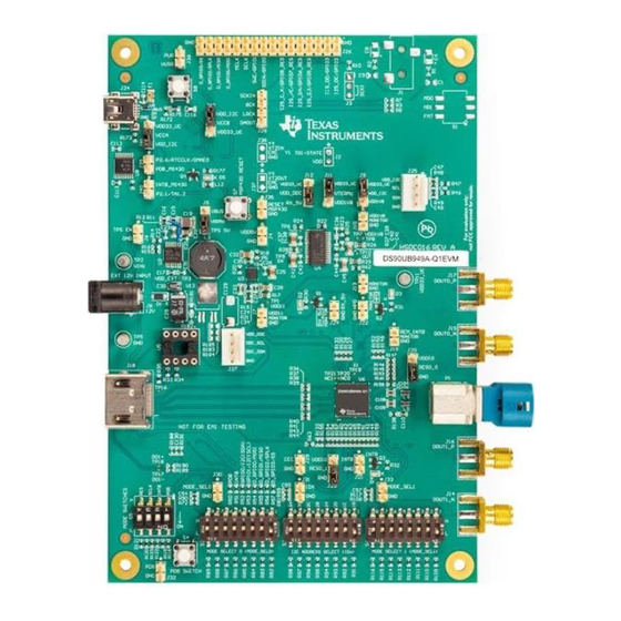
Texas Instruments DS90UB949A-Q1EVM User Manual (63 pages)
Brand:
Texas Instruments
| Category:
Control Unit
| Size: 6.46 MB
Table of Contents
Table of Contents
2
DS90UH949A-Q1EVM or DS90UB949A-Q1EVM User's Guide
5
General Description
5
Features
6
System Requirements
6
Contents of the Demo Evaluation Kit
6
Applications Diagram
7
Typical Configuration
7
Quick Start Guide
8
Interfacing to the EVM
9
Default Jumper Settings
10
Default Switch Settings
10
Default Board Jumper Settings
10
Default Board Switch Settings
10
Demo Board Connections
11
Power Supply
11
FPD-Link III Output Signals P1 (HSD Connector)
11
Alternative SMA FPD-Link III Output Signals (Note: Smas Are Not Connected by Default from the Factory)
11
HDMI Input Signals
11
USB2ANY Connector
11
I2C/CCI Interface Header J25
11
Gpio/Audio Interface
12
SPI/D_GPIO Interface
12
MODE_SEL[1:0] Settings
12
Configuration Select (MODE_SEL0) -- SW-DIP8 - S2
12
Configuration Select (MODE_SEL1) - SW-DIP8 - S6
13
IDX SW-DIP8 - S3
13
ALP Software Setup
14
System Requirements
14
Download Contents
14
Installation of the ALP Software
14
Start-Up - Software Description
15
Launching ALP
15
Initial ALP Screen
16
Follow-Up Screen
16
Information Tab
17
ALP Information Tab
17
HDMI Tab
18
ALP HDMI Tab
18
Pattern Generator Tab
19
ALP Pattern Generator Tab
19
Registers Tab
20
ALP Registers Tab
20
Registers Tab - Address 0X00 Selected
21
ALP Device ID Selected
21
Registers Tab - Address 0X00 Expanded
22
ALP Device ID Expanded
22
Scripting Tab
23
ALP Scripting Tab
23
Troubleshooting ALP Software
24
ALP Loads the Incorrect Profile
24
USB2ANY Setup
24
Remove Incorrect Profile
24
Add Correct Profile
25
Finish Setup
25
ALP Does Not Detect the EVM
26
ALP no Devices Error
26
Windows 7, ALP USB Driver
26
ALP in Demo Mode
27
ALP Preferences Menu
27
Typical Connection and Test Equipment
28
Typical Test Setup for Video Application
28
Typical Test Setup for Evaluation
28
Equipment References
29
Cable References
29
Bill of Materials
30
EVM PCB Schematics
39
Schematic - Block Diagram
39
Schematic - DS90UH949A-Q1 and Power Decoupling
40
Schematic - MSP430
41
Schematic - HDMI, HSD, SMA, I2C, DDC, CEC and GPIO/I2S/SPI Connectors
43
Schematic - Leds
44
Schematic - Audio (Not Populated)
45
Schematic - Power Regulators
46
Schematic - Hardware
47
Board Layout
48
Board Layer - Top Overlay
48
Board Layer - Top Solder
49
Board Layer - Top
50
Board Layer - Ground-1
51
Board Layer - Signal Layer
52
Board Layer - Power Split/Gnd
53
Board Layer - Ground
54
Board Layer - Bottom
55
Board Layer - Bottom Solder
56
Revision History
57
Advertisement
Advertisement
Related Products
Texas Instruments DS90Ux941AS-Q1EVM
Texas Instruments DS160PR412-421EVM
Texas Instruments DAC7571
Texas Instruments DAC7574
Texas Instruments DP83869EVM
Texas Instruments DAC38RF82EVM
Texas Instruments DAC5674 EVM
Texas Instruments DAC900EVM
Texas Instruments DAC902EVM
Texas Instruments DAC904EVM
Texas Instruments Categories
Motherboard
Control Unit
Microcontrollers
Computer Hardware
Calculator
More Texas Instruments Manuals
Login
Sign In
OR
Sign in with Facebook
Sign in with Google
Upload manual
Upload from disk
Upload from URL