Sign In
Upload
Manuals
Brands
Texas Instruments Manuals
Accessories
AWRL6432BOOST
Texas Instruments AWRL6432BOOST Manuals
Manuals and User Guides for Texas Instruments AWRL6432BOOST. We have
1
Texas Instruments AWRL6432BOOST manual available for free PDF download: User Manual
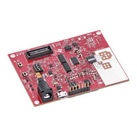
Texas Instruments AWRL6432BOOST User Manual (23 pages)
FR4-Based Low Power 60 GHz mm-Wave Sensor EVM
Brand:
Texas Instruments
| Category:
Accessories
| Size: 1.66 MB
Table of Contents
Table of Contents
1
Abstract
1
Getting Started
2
Key Features
2
Kit Contents
2
Mmwave out of Box Demo
2
Hardware
3
Figure 3-1. XWRL6432BOOST Top View
3
Figure 3-2. XWRL6432BOOST Bottom View
4
Figure 3-3. Salient Features of EVM
4
Block Diagram
5
Figure 3-4. Salient Features of EVM (Bottom Side)
5
Figure 3-5. Functional Block Diagram
5
EVM Mux Block Diagram
7
Figure 4-1. Muxing Options for the EVM
7
PCB Storage and Handling Recommendations
8
Higher Power Demanding Applications
8
XWRL6432BOOST Antenna
9
PCB Material
9
Figure 6-1. TX and Rx Antennas of the EVM
9
Figure 6-2. Virtual Antenna Array
10
Figure 6-3. Azimuth Antenna Radiation Patterns
10
Switch Settings
11
Figure 6-4. Elevation Antenna Radiation Patterns
11
Figure 6-5. S1 Switch for Various Mode
11
Leds
12
Figure 6-6. S4 Switch for Various Mode Settings
12
Figure 6-7. SOP Switches
12
Connectors
13
USB Connector
13
DCA1000 HD Connector
13
Figure 6-8. USB Connector (J5)
13
Booster Pack Connector for the Launchpad Connectivity
14
CANFD Connector
14
Figure 6-9. DCA1000 HD Connector
14
Figure 6-10. Booster Pack Connector
14
Figure 6-11. CANFD Connector
15
Figure 6-12. Analog Mux for the CAN PHY
15
LIN PHY Connection
16
Figure 6-13. CAN FD PHY Used in the EVM
16
Figure 6-14. LIN Header and PHY Interface
16
Figure 6-15. LIN PHY Interface
16
I2C Connections
17
XDS110 Interface
17
Figure 6-16. Virtual COM Port
17
Flashing the Board
18
DCA1000EVM Mode
18
Figure 6-17. EVM in Functional Mode Using Standalone Operation
18
Figure 6-18. DCA1000EVM Mode Top View
19
Figure 6-19. DCA1000EVM Mode Side View
20
Figure 6-20. DCA1000 CMOS to LVDS Conversation for Data Lines
21
Figure 6-21. DCA1000 CMOS to LVDS Conversation for Clock and Control Lines
21
Software, Development Tools, and Example Code
22
XWRL6432 Demo Visualization Getting Started
22
TI E2E Community
22
References
22
Revision History
22
Advertisement
Advertisement
Related Products
Texas Instruments AWR1642
Texas Instruments AWR1642BOOST-ODS
Texas Instruments AWRL6432AOPEVM
Texas Instruments AWR1243
Texas Instruments AWR1443BOOST
Texas Instruments AWR1642BOOST
Texas Instruments AWR1843
Texas Instruments AWR1843AOP EVM
Texas Instruments AWR2944EVM
Texas Instruments AWR2944
Texas Instruments Categories
Motherboard
Control Unit
Microcontrollers
Computer Hardware
Calculator
More Texas Instruments Manuals
Login
Sign In
OR
Sign in with Facebook
Sign in with Google
Upload manual
Upload from disk
Upload from URL