Sign In
Upload
Manuals
Brands
Teledyne Manuals
Digital Camera
Princeton Instruments PI-MAX 3
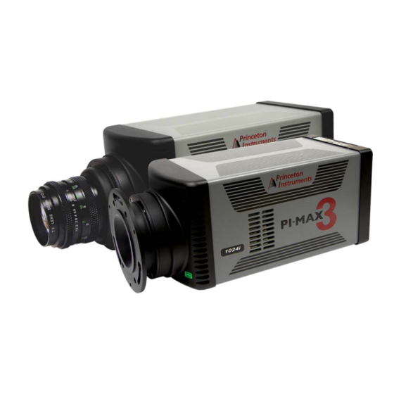
Teledyne Princeton Instruments PI-MAX 3 Manuals
Manuals and User Guides for Teledyne Princeton Instruments PI-MAX 3. We have
1
Teledyne Princeton Instruments PI-MAX 3 manual available for free PDF download: System Manual
Teledyne Princeton Instruments PI-MAX 3 System Manual (250 pages)
Brand:
Teledyne
| Category:
Digital Camera
| Size: 7.85 MB
Table of Contents
Table of Contents
3
Alarm
13
Attention
13
Unigen™ II Coating
14
Chapter 1 About this Manual
15
Intended Audience
15
Related Documentation
15
Table 1-1: Related Documentation
15
Document Organization
16
Conventions Used in this Document
17
Table 1-2: Terminology Conventions Used
17
PI-MAX3 Safety Information
18
Safety Related Symbols Used in this Manual
18
Audible Alarm
19
Intensifier Modes and Safety
19
High Intensity Light Damage
20
Precautions
20
Chapter 2 PI-MAX3 Camera System
21
Figure 2-2: Typical PI-MAX3 Camera
22
Mount Adapters
22
PI-MAX3 Camera
22
Cooling
23
Extender Bracket Kit
23
Gige Ethernet Card
23
Figure 2-3: PI-MAX3 Rear-Panel Connectors
24
PI-MAX3 Rear-Panel Connectors and Indicators
24
Table 2-1: PI-MAX3 Rear-Panel Connectors and Indicators
25
Power
26
Figure 2-4: PI-MAX3 Power Supply Connectors and Indicators
27
Table 2-2: PI-MAX3 Power Supply Connectors and Indicators
27
Application Software
28
Cables
29
Optional Accessories
29
Table 2-3: Standard PI-MAX3 Camera System Cables
29
Camera
30
Cleaning Optical Surfaces: Protective Window
30
Cleaning Optical Surfaces: Unigen™II Coating
30
Coolcube II Coolant Circulator
30
PI-MAX3 Camera and System Maintenance
30
Spectrograph
30
Flushing and Refilling the CCD Chamber
31
Repairs
31
Chapter 3 PI-MAX3 Image Acquisition
33
Image Acquisition Process
34
Chapter 4 Installation Overview
35
Table 4-1: PI-MAX3 Installation Actions
35
Figure 4-1: Block Diagram: PI-MAX3
37
System Block Diagrams
37
Pi-Max
38
Chapter 5 System Setup
39
Unpack the System
39
Examine Equipment and Verify Parts Inventory
40
Imaging Applications
41
Mount the PI-MAX3
41
Install Application Software
42
Install Winx/32
42
Spectroscopy Applications
42
Figure 5-1: Typical Winview/32 Setup Dialog: Select Installation Type
43
Figure 5-2: Typical Lightfield Installation Wizard Dialog
44
Install Lightfield
44
Connect PI-MAX3 to Coolcube II
45
Figure 5-3: Typical Coolcube II Coolant Circulator
45
Configure Default System Parameters
46
Connect PI-MAX3 to Dry Nitrogen Source
46
Winx/32 Applications (Version 2.5.25.X and Higher)
46
Figure 5-4: Typical Camera Detection Wizard - Welcome Dialog
47
Lightfield Applications
48
Chapter 6 First Light
49
Required Equipment
49
Winx/32 First Light
49
Procedure
50
Figure 6-2: Typical Winx/32 Supersynchro
52
Figure 6-3: Typical Winx/32 Supersynchro
52
Figure 6-4: Typical Winx/32 Repetitive Gating Setup Dialog
53
Figure 6-5: Typical Winx/32 Experiment Setup Main Tab Dialog
54
Figure 6-6: Typical Winx/32 Experiment Setup ADC Tab Dialog
54
Figure 6-7: Typical Winx/32 Experiment Setup
55
Figure 6-8: Typical Winx/32 First Light Acquired Image
56
Figure 6-9: Typical Winx/32 First Light Acquired Image, Reversed/Flipped
56
Lightfield First Light
58
Procedure
58
Required Equipment
58
Figure 6-10: Typical Lightfield Available Devices Area
59
Figure 6-11: Typical Lightfield Experiment Devices Area with PI-MAX3
60
Figure 6-12: Typical Lightfield Online Corrections Orientation Indicator
61
Figure 6-13: Typical Lightfield Experiment Workspace
61
Figure 6-14: Typical Lightfield View Tab with Image
62
Chapter 7 Operation
63
Dark Charge
64
Pre-Exposure Removal of Accumulated Charge
64
Winx/32 System On/Off Sequences
64
Cleaning
65
Figure 7-2: Timing Diagram: Internal Trigger Mode, Clean Cycles
65
Phosphor Decay Delay
67
Cooling Method
68
Figure 7-3: Typical Winx/32 Hardware Setup Dialog: Phosphor Decay Delay
68
Figure 7-4: Typical Lightfield Common Acquisition Settings Advanced
68
Temperature Control
68
Air-Cooling
69
Supplemental Circulating Coolant
69
Exposure
70
Exposure with an Image Intensifier
70
Setting the Temperature
70
Background Subtraction
71
Saturation
71
Readout of the Array
72
Figure 7-5: Typical Interline CCD Readout
73
Interline CCD Readout
73
Figure 7-6: Non-Overlapped Mode Exposure and Readout
74
Non-Overlapped Mode Exposure and Readout
74
Interline Readout Rate
75
Full Frame CCD Readout
76
Table 7-1: Readout Rates: Kodak 1024 X 1024 Array, 16 Mhz Dual Port Mode
76
Binned Readout (Hardware Binning)
78
Table 7-2: Readout Rates: E2V CCD30-11 1024 × 256 Array at 2 Mhz
78
CCD Type and Readout Port(S)
79
Figure 7-8: Dual Port Readout: 2 X 2 Binning, Interline CCD
79
Figure 7-10: Single Port Readout: 2 X 2 Binning, Full Frame CCD
80
Figure 7-9: Typical Lightfield ROI Expander: Dual Port Readout, 2 X
80
Figure 7-11: Typical Winx/32 Experiment Setup ROI Setup Tab Dialog
81
Figure 7-12: Lightfield: Edit Regions of Interest Dialog
82
Figure 7-13: Single Port Readout: 2 X 2 Binning, Partial Frame, Interline CCD
83
Figure 7-14: Lightfield Region of Interest Expander: Dual Port Readout
84
Software Binning
85
Controller Gain {Analog Gain
86
Digitization
86
Figure 7-15: Typical Winx/32 Hardware Setup
87
Figure 7-16: Timing Diagram: Logic out Control, Key Control Signals
87
Logic out Control
87
Experiment Setup ► Main Tab
89
Figure 7-17: Typical Winx/32 Experiment Setup Main Tab Dialog
89
Winx/32 Experiment Setup
89
Experiment Setup ► Timing Tab
90
Figure 7-18: Typical Winx/32 Experiment Setup Timing Tab Dialog
90
Figure 7-19: Flowcharts: Fast Mode Versus Safe Mode
92
Common Acquisition Settings Expander
93
Figure 7-20: Typical Lightfield Common Acquisitions Settings Expander
93
Lightfield Experiment Setup
93
Figure 7-21: Typical Lightfield Region of Interest Expander
94
Region of Interest Expander
94
Figure 7-22: Typical Lightfield Trigger Expander: Internal Trigger Source
95
Figure 7-23: Typical Lightfield Trigger Expander: External Trigger Source
95
Trigger Expander
95
Figure 7-24: Typical Lightfield Supersynchro Timing Expander
96
Supersynchro Expander
96
Figure 2-1: Typical PI-MAX3 System Components
21
Figure 3-1: Primary Components of an Intensifier-CCD
33
Data Acquisition Sequence
63
Figure 7-1: Block Diagram: Signal Path in Standard PI-MAX3 System
63
Chapter 8: Winx/32 and Gated Operation
97
Precautionary Measures
98
Intensifier Modes and Safety
98
Alarm
99
Timing Mode
99
MCP Bracket Pulsing
100
Figure 8-1: Timing: Bracket Pulsing
100
Bracket Pulsing in LIF Measurements
101
Bracket Pulsing in Nanosecond Pump Probe Experiments
101
Limitations of Bracket Pulse Gating
102
Impact of Bracket Pulsing on Delay
102
Setup
103
Figure 8-2: Timing Diagram: PI-MAX3 MCP Bracket Pulsing
103
Additional Experiments
104
Figure 8-3: Typical PI-MAX3 Experiments
104
Swept Gate Experiment [Fixed Width; Variable Delay]
105
Experiment Is Master Clock
105
Figure 8-4: Block Diagram: Swept Gate Experiment
105
Figure 8-5: Timing Diagram: Swept Gate Experiment
106
Figure 8-6: Typical Hardware Setup: Controller/Camera Tab
106
Figure 8-7: Typical Define Spectrograph Dialog
107
Figure 8-8: Typical Install/Remove Spectrographs Dialog
108
Figure 8-9: Typical Define Spectrograph Dialog: Main Tab [Acton Sp300I]
108
Figure 8-10: Typical Move Spectrograph Dialog
109
Figure 8-11: Typical Experiment Setup Dialog: Main Tab
109
Figure 8-12: Typical Experiment Setup Dialog: Timing Tab
110
Figure 8-13: Typical Experiment Setup Dialog: ADC Tab
110
Figure 8-14: Typical Experiment Setup Dialog: ROI Setup Tab
111
Figure 8-15: Typical Supersynchro Dialog: Trigger in Tab
111
Figure 8-16: Typical Supersynchro Dialog: Trigger in Tab
112
Figure 8-17: Typical Supersynchro Dialog: Gating Tab
113
Figure 8-18: Typical Sequential Gating Setup Dialog
113
Figure 8-19: Typical Width/Delay Sequence Dialog
114
Figure 8-20: Typical Supersynchro Dialog: Trigger out Tab
115
Figure 8-21: Typical Experiment Setup Dialog: Timing Tab
116
Figure 8-22: Typical Experiment Setup Dialog: Main Tab
117
Syncmaster1 as Master Clock
118
Figure 8-23: Typical 3D Experiment Results
118
Figure 8-24: Block Diagram: PI-MAX3 Syncmaster1 as Master Clock
118
Swept Gate Experiment [Variable Width, Variable Delay]
119
Figure 8-25: Timing Diagram: PI-MAX3 Syncmaster1 as Master Clock
119
Static Gate Experiment [Fixed Width, Fixed Delay]
120
Single Shot Experiment
120
Figure 8-26: Typical Repetitive Gating Setup Dialog
120
Table 8-2: Sample Single Shot Experiment Time Budget
120
Figure 8-27: Block Diagram: Single Shot
121
Figure 8-28: Typical Cleans and Skips Default Values
121
Figure 8-29: Typical Experiment Setup Dialog: Main Tab, Gain Configuration
122
Figure 8-30: Repetitive Gating Setup: 100 Ns Width, 10 Ns Delay
122
Figure 8-31: Single Shot Result: Fluorescence Spot, 100 Ns Width
123
Figure 8-32: Single Shot Result: Fluorescence Spot, 100 Ns Width
123
Chapter 9: Lightfield and Gated Operation
125
Precautionary Measures
126
Intensifier Modes and Safety
126
Alarm
127
Timing Mode
127
MCP Bracket Pulsing
128
Figure 9-1: Timing: Bracket Pulsing
128
Bracket Pulsing in LIF Measurements
129
Bracket Pulsing in Nanosecond Pump Probe Experiments
129
Limitations of Bracket Pulse Gating
130
Impact of Bracket Pulsing on Delay
130
Setup
131
Figure 9-2: Timing Diagram: PI-MAX3 MCP Bracket Pulsing
131
Additional Experiments
132
Figure 9-3: Typical PI-MAX3 Experiments
132
Swept Gate Experiment [Fixed Width; Variable Delay]
133
Experiment Is Master Clock
133
Figure 9-4: Block Diagram: Swept Gate Experiment
133
Figure 9-5: Timing Diagram: Swept Gate Experiment
134
Figure 9-6: Typical Sensor Cleaning Fly-Out Panel
134
Figure 9-7: Typical Spectrometer Expanders
135
Figure 9-8: Typical Region of Interest Expander: Full Sensor Selected
136
Figure 9-9: Typical Common Acquisition Settings Expander
136
Figure 9-10: Typical Analog to Digital Conversion Expander
137
Figure 9-11: Typical Trigger Expander: Internal Trigger Source Selected
137
Figure 9-12: Typical Region of Interest Expander: Full Sensor Binned
138
Figure 9-13: Typical Trigger Expander: External Trigger Source
138
Figure 9-14: Typical Supersynchro Timing Expander
139
Figure 9-15: Typical Supersynchro Timing with Syncmaster on
140
Syncmaster1 as Master Clock
141
Figure 9-16: Typical Experiment Results with Frame Cross-Section Active
141
Figure 9-17: Block Diagram: PI-MAX3 Syncmaster1 as Master Clock
141
Swept Gate Experiment [Variable Width, Variable Delay]
142
Figure 9-18: Timing Diagram: PI-MAX3 Syncmaster1 as Master Clock
142
Static Gate Experiment [Fixed Width, Fixed Delay]
143
Single Shot Experiment
143
Figure 9-19: Typical Supersynchro Timing Expander: Repetitive Gating
143
Table 9-2: Sample Single Shot Experiment Time Budget
143
Figure 9-20: Block Diagram: Single Shot
144
Figure 9-21: Typical Cleans and Skips Default Values
144
Figure 9-22: Typical Common Acquisition Settings Expander: Configure
145
Figure 9-23: Repetitive Gating Setup: 100 Ns Width, 25 Ns Delay
145
Figure 9-24: Single Shot Result: Fluorescence Spot, 100 Ns Width
146
Figure 9-25: Single Shot Result: Fluorescence Spot, 100 Ns Width
146
Chapter 10: Timing Generator Pulses and Sequences
147
Pulse Set
147
Figure 10-1: Typical Pulse Set
147
Supported Timing Generator Trigger Modes
148
Single Sequence
148
Figure 10-2: Timing Diagram: Trigger Per Pulse
148
Figure 10-3: Single Sequence with Three Repetitions
148
Supported Timing Generator Trigger Modes
149
Time Stamping
149
Figure 10-4: Timing Diagram: Sequence with 3 Repetitions and
149
Pi-Max
150
Chapter 11: Winx/32 and Dual Image Feature (DIF)
151
Requirements
151
Interline CCD Operation
151
Timing Modes
152
Configure a Single Trigger DIF Experiment
152
Figure 11-1: Typical System Block Diagram: DIF Operation
152
Figure 11-2: Timing Diagram: DIF Operation, Single Trigger
152
Figure 11-3: Typical Hardware Setup Controller/Camera Tab
153
Figure 11-4: Typical Experiment Setup
154
Figure 11-5: Typical Experiment Setup
154
Figure 11-6: Typical Pulsers Dialog
155
Figure 11-7: Typical Supersynchro Dialog
155
Figure 11-8: Typical DIF Gating Setup Dialog
156
Figure 11-9: Typical Supersynchro Dialog: Trigger in Tab
156
Figure 11-10:Typical Supersynchro Dialog: Trigger out Tab
157
Configure a Dual Trigger DIF Experiment
158
Figure 11-11: Typical System Block Diagram: DIF Operation
158
Figure 11-12:Timing Diagram: DIF Operation, Dual Trigger
158
Figure 11-13: Typical Hardware Setup Controller/Camera Tab
159
Figure 11-14:Typical Experiment Setup
160
Figure 11-15: Typical Experiment Setup
160
Figure 11-16:Typical Pulsers Dialog
161
Figure 11-17:Typical Supersynchro Dialog
161
Figure 11-18:Typical DIF Gating Setup Dialog: Dual Trigger
162
Figure 11-19:Typical Supersynchro Dialog: Trigger in Tab
162
Figure 11-20:Typical Supersynchro Dialog: Trigger out Tab
163
Tips and Tricks
164
Chapter 12: Lightfield and Dual Image Feature (DIF)
165
Requirements
165
Figure 12-1: Typical Readout Expander
165
Interline CCD Operation
166
Figure 12-2: Typical Common Acquisition Settings Expander
166
Trigger Configuration
167
Figure 12-3: Typical Trigger Expander
167
Configure a Single Trigger DIF Experiment
168
Figure 12-4: Typical Supersynchro Timing Expander: DIF
168
Figure 12-5: Typical System Block Diagram: DIF Operation
168
Figure 12-6: Timing Diagram: DIF Operation, Single Trigger
169
Configure a Dual Trigger DIF Experiment
171
Figure 12-7: Typical System Block Diagram: DIF Operation
171
Figure 12-8: Timing Diagram: DIF Operation, Dual Trigger
171
Tips and Tricks
173
Chapter 13: MCP Gating
175
Setup and Operation
175
Gain Variation
175
Fluorescence Experiment
175
Hardware Configuration for MCP Gated Operation
176
Figure 13-1: Hardware Block Diagram: MCP Gated Operation
176
Figure 13-2: Timing Diagram: MCP Gated Operation
177
Chapter 14: Picosecond Option
179
Activating Picosecond Operation
179
Gain and Gate Width
179
MONITOR Operation
180
Repetition Rate Issues
180
Timing
180
Table 14-1: Typical PI-MAX3: 1024I Picosecond Operation Data: Sustained
180
Methods for Finding a Short Optical Pulse
181
Example
181
Chapter 15: Tips and Tricks
183
Overexposure Protection
183
Signal Delay
183
Time Budgets
184
Measuring Coincidence
184
Adjusting the Signal Delay
185
Optimizing the Gate Width and Delay
186
Lasers
186
Free Running Lasers
186
Triggered Lasers
187
Jitter
187
Inhibiting the Pulser During Readout
187
Lens Performance
188
Throughput
188
Depth of Field
188
Baseline Signal
189
Temperature Lock
189
Intensifier Alarm
189
Chapter 16: Troubleshooting
191
Table 16-1: List of Recommended Troubleshooting Procedures
191
Alarm Sounds Repetitively
192
Alarm Sounds Sporadically
192
Baseline Signal Suddenly Changes by > 1000 ADU
192
Camera Is Not Responding
192
Camera Stops Working
193
Cooling Troubleshooting
193
Temperature Lock Cannot be Achieved or Maintained
193
Gradual Deterioration of Cooling Capability
194
Data Loss or Serial Violation
194
Error Occurs at Computer Power up
194
Ethernet Network Is Not Accessible
194
Winx/32 Applications
194
Lightfield Applications
195
Figure 16-1: Typical Winx/32 Ebus Driver Installation Tool Dialog
195
Figure 16-2: Typical Lightfield Ebus Driver Installation Tool Dialog
195
Excessive Readout Noise
196
Appendix A: Technical Specifications
197
Camera Specifications
197
Table A-1: CCD Specifications
197
Figure A-1: Typical Phosphor Emission Spectra
199
AUX I/O Connector Pinout
201
Figure A-2: Typical AUX I/O Cable
201
Table A-2: AUX I/O Cable Leads
201
Figure A-3: AUX I/O Connector Pinout
202
Table A-3: AUX I/O Connector Pinout and Signal Description
202
Power Requirements
204
Environmental Requirements
204
Ventilation
205
Internal Pulser
205
Intensifier Quantum Efficiency
206
Figure A-4: QE Curve: Gen II Intensifier
206
Figure A-5: QE Curve: Gen III Filmless Intensifier
206
Coolcube II Circulator
207
Minimum Host Computer Requirements
208
Appendix B: Outline Drawings
209
Pi-Max3
209
Figure B-1: Outline Drawing: PI-MAX3 with C-Mount Adapter
209
Figure B-2: Outline Drawing: PI-MAX3 with F-Mount Adapter
210
Figure B-3: Outline Drawing: PI-MAX3 with Spectroscopy-Mount Adapter
211
PI-MAX3 Power Supply
212
Figure B-4: Outline Drawing: PI-MAX3 Power Supply
212
Coolcube II Circulator
213
Figure B-5: Outline Drawing: Coolcube II Circulator
213
Appendix C: Winspec/32 and Lightfield Cross References
215
Winspec/32-To-Lightfield Terminology
215
Table C-1: Winspec/32-To-Lightfield Cross Reference
215
Lightfield to Winspec/32
217
Table C-2: Lightfield-To-Winspec/32 Cross Reference
217
Appendix D: Extender Bracket Kit
219
Figure D-1: Extender Bracket Kit Mounted to PI-MAX3
219
Appendix E: Mounting and Focusing C- and F-Mount Lenses
221
Lens Mounting
221
Figure E-1: F-Mount (Nikon) Lens Adapter
221
Mounting Orientation
222
Len Focusing
222
Appendix F: C-, F-, and Spectroscopy-Mount Adapters
223
Accessory Kits
223
PI-MAX3 18 MM Tube
223
PI-MAX3 25 MM Tube
223
Figure F-1: Screwdriver with Reversible Flat and Phillips Tips
223
Adapter Kits
224
PI-MAX3 to Teledyne Acton Research Spectrograph Quick Start Guides
224
Standard C-, F-, and Spectroscopy-Mount Adapters
224
Table F-1: Adapter Kit Information
224
Spectroscopy-Mount for NVUV Cameras
225
Figure F-2: PI-MAX3 Mount Adapters
225
Figure F-3: O-Ring Positions for PI-MAX3 NVUV Cameras
225
Optical Distance from Mounting Face to Image Plane
226
Appendix G: Spectrograph Adapters
227
Spectrograph-Detector Focus
227
Teledyne Acton Research Series Spectrograph
227
Isoplane SCT-320 Spectrograph
229
PI-MAX3 (3.60" 3-Hole Slotted Flange) to Teledyne Acton Research
231
Series Spectrograph
231
Required Tools
231
Procedure
231
PI-MAX3 to Teledyne Acton Research (C-Mount Adapter)
233
Figure G-2: PI-MAX3 to Teledyne Acton Research with C-Mount Adapter
233
Table G-1: Required Hardware: PI-MAX3 to Teledyne Acton Research with C-Mount
233
PI-MAX3 to Isoplane SCT-320
235
Figure G-3: PI-MAX3 to Isoplane SCT-320
235
Table G-2: Required Hardware: PI-MAX3 to Isoplane SCT-320
235
Appendix H: Glossary
237
Warranty and Service
245
Limited Warranty
245
Basic Limited One (1) Year Warranty
245
Limited One (1) Year Warranty on Refurbished or Discontinued Products
245
XP Vacuum Chamber Limited Lifetime Warranty
245
Sealed Chamber Integrity Limited 12 Month Warranty
246
Vacuum Integrity Limited 12 Month Warranty
246
Image Intensifier Detector Limited One Year Warranty
246
X-Ray Detector Limited One Year Warranty
246
Software Limited Warranty
246
Owner's Manual and Troubleshooting
247
Your Responsibility
247
Contact Information
248
Advertisement
Advertisement
Related Products
Teledyne Princeton Instruments Sophia-XO
Teledyne Princeton Instruments PI-MTE
Teledyne Princeton Instruments Nano-XF
Teledyne Princeton Instruments NIRvana
Teledyne Princeton Instruments Quad-RO
Teledyne Princeton Instruments NIRvana HS
Teledyne ProEM Series
Teledyne ProEM:512B
Teledyne ProEM:512BK
Teledyne ProEM:1024B
Teledyne Categories
Measuring Instruments
Analytical Instruments
Digital Camera
Test Equipment
Laboratory Equipment
More Teledyne Manuals
Login
Sign In
OR
Sign in with Facebook
Sign in with Google
Upload manual
Upload from disk
Upload from URL