Sign In
Upload
Manuals
Brands
TDK-Lambda Manuals
Power Supply
Genesys GEN60-40
TDK-Lambda Genesys GEN60-40 Manuals
Manuals and User Guides for TDK-Lambda Genesys GEN60-40. We have
2
TDK-Lambda Genesys GEN60-40 manuals available for free PDF download: Technical Manual, User Manual
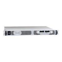
TDK-Lambda Genesys GEN60-40 Technical Manual (88 pages)
1U PROGRAMMABLE DC POWER SUPPLIES
Brand:
TDK-Lambda
| Category:
Power Supply
| Size: 3.36 MB
Table of Contents
Table of Contents
7
Warranty
11
Safety Instructions
12
French
15
German
17
Italian
19
Portuguese
21
Spanish
23
Chapter 1 General Information
25
User Manual Content
25
Introduction
25
General Description
25
Models Covered by this Manual
25
Features and Options
25
Multiple Output Power System
26
Control Via the Serial Communication Port
26
Analog Voltage Programming and Monitoring
26
Parallel Operation
26
Output Connections
26
Cooling and Mechanical Construction
26
Accessories
27
Included Accessories
27
Optional Communication Cables (See Section 7.5)
27
AC Cables
27
Chapter 2 Specifications
28
Output Rating
28
Auxiliary Outputs
28
Input Characteristics
28
Constant-Voltage Mode
28
Constant-Current Mode
28
Analog Programming and Monitoring
28
PROGRAMMING and READBACK (RS-232/485, Optional LAN, IEEE, USB Interface)
28
Protective Functions
29
Front Panel
29
Environmental Conditions
29
Mechanical Construction
29
Emc
29
Safety
29
Supplemental Characteristics
30
Genesystm 2400W Power Supply Outline Drawing
31
Chapter 3 Installation
32
General
32
Preparation for Use
32
Initial Inspection
32
Rack Mounting
32
To Install the Power Supply in a Rack
32
Rack-Mount Slides (Optional)
33
Location, Mounting and Cooling
33
Ac Source Requirements
33
Ac Input Power Connection
33
AC Input Connector
34
AC Input Cord
34
AC Input Wire Connection
34
Turn-On Checkout Procedure
35
General
35
Prior to Operation
35
Constant-Current Check
36
Constant-Voltage Check
36
OVP Check
36
UVL Check
36
Address Setting
37
Foldback Check
37
Baud Rate Setting (RS-232 and RS-485 Only)
37
Connecting the Load
37
Load Wiring
37
Current Carrying Capacity
37
Noise and Impedance Effects
38
Wire Termination
38
Inductive Loads
39
Making the Load Connections
39
Connecting Single Loads, Local Sensing (Default Configuration)
42
Connecting Single Loads, Remote Sensing
42
Connecting Multiple Loads, Radial Distribution Method
42
Multiple Load Connection with Distribution Terminals
43
Grounding Outputs
43
Local and Remote Sensing
44
Sense Wiring
44
Local Sensing
44
Remote Sensing
45
J2 Sense Connector Technical Information
45
Repackaging for Shipment
45
Chapter 4 Front and Rear Panel Controls and Connectors
46
Introduction
46
Front Panel Controls and Indicators
46
Rear Panel
48
Auxiliary Power Supply
49
Rear Panel Sw1 Setup Switch
49
SW1 DIP-Switch Position Function
50
Resetting the SW1 DIP-Switch
50
Rear Panel J1 Programming and Monitoring Connector
51
Making J1 Connections
51
Chapter 5 Local Operation
53
Introduction
53
Standard Operation
53
Constant-Voltage Mode
53
Constant-Current Mode
53
Automatic Crossover
54
Over-Voltage Protection (Ovp)
54
Setting the OVP Level
54
Activated OVP Protection Indications
54
Resetting the OVP Circuit
54
Under Voltage Limit (Uvl)
54
Setting the Output UVL Level
54
Foldback Protection
55
Setting the Foldback Protection
55
Resetting Activated Foldback Protection
55
Output On/Off Control
55
Output Shut-Off (So) Control Via Rear Panel J1 Connector
55
Enable/Disable Control Via Rear Panel J1 Connector
56
CV/CC Signal
56
Ps_Ok Signal
56
Safe-Start and Auto-Restart Modes
57
Auto-Restart Mode
57
Safe-Start Mode
57
Over-Temperature Protecton (Otp)
57
Last Setting Memory
57
Series Operation
57
Series Connection for Increased Output Voltage
58
Series Connection for Positive and Negative Output Voltage
59
Parallel Operation
60
Basic Parallel Operation
60
Advanced Parallel Operation
60
Daisy-Chain Connection
62
Front Panel Locking
63
Unlocked Front Panel
63
Locked Front Panel
63
Chapter 6 Remote Analog Programming
64
Introduction
64
Local/Remote Analog Control
64
Local/Remote Analog Indication
64
Remote Voltage Programming of Output Voltage and Output Current
65
Resisitive Programming of Output Voltage and Current Limit
66
Remote Monitoring of Output Voltage and Current
67
Chapter 7 Rs-232 & Rs-485 Remote Control
68
Introduction
68
Configuration
68
Default Setting
68
Address Setting
68
RS-232 or RS-485 Selection
68
Baud Rate Setting
68
Setting the Unit into Remote or Local Mode
68
Front Panel in Remote Mode
69
RS-232/RS-485 Port in Local Mode
69
Rear Panel Rs-232/Rs-485 Connector
69
Connecting Power Supplies to Rs-232 or Rs-485 Bus
70
Single Power Supply
70
Multi-Power Supply Connection to RS-232 or RS-485 Bus
71
Communication Interface Protocol
71
Data Format
71
Addressing
71
End of Message
71
Command Repeat
71
Checksum
72
Acknowledge
72
Error Message
72
Backspace
72
Error Messages
72
Command Set Description
72
General Guide
72
Command Set Categories
73
Initialization Control Commands
73
ID Control Commands
73
Output Control Commands
73
Global Output Commands
75
Status Control Commands
76
Status, Error and Srq Registers
77
General
77
Conditional Registers
78
Service Request: Enable and Event Registers
79
Serial Communication Test Set-Up
81
Equipment
81
PC Set-Up
81
Power Supply Set-Up
81
Communication Test
81
Chapter 8 Isolated Analog Programming Option
82
Introduction
82
Specifications
82
0-5V/0-10V Option (Pn: Is510)
82
4-20Ma Option (PN: IS420)
82
Isolated Programming & Monitoring Connector
83
Setup and Operating Instructions
84
Setting up the Power Supply for 0-5V/0-10V Isolated Programming and Monitoring
84
Setting up the Power Supply for 4-20Ma Isolated Programming and Monitoring
84
Parallel Operation with Isolated Analog Option
85
Setting up the Master Unit
85
Setting up the Slave Unit
85
Chapter 9 Maintenance
86
Introduction
86
Units under Warranty
86
Periodic Maintenance
86
Adjustments and Calibration
86
Parts Replacement and Repairs
86
Troubleshooting
86
Fuse Rating
87
Index (User's Manual)
88
Advertisement
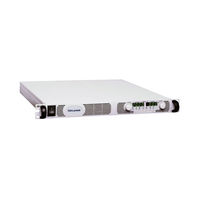
TDK-Lambda Genesys GEN60-40 User Manual (82 pages)
Programmable DC Power Supplies 2.4kW in 1U Built in RS-232 & RS-485 Interface Advanced Parallel Operation
Brand:
TDK-Lambda
| Category:
Power Supply
| Size: 4.11 MB
Table of Contents
Gen20
4
Gen8
5
Table of Contents
6
Introduction
8
Regulatory Notices
11
Safety Instructions
12
Features and Options
16
General Description
16
Models Covered
16
Chapter 1 General Information
16
Analog Voltage Programming and Monitoring
17
Control Via the Serial Communication Port
17
Multiple Output Power System
17
Output Connections
17
Parallel Operation
17
AC Cables
18
Accessories
18
Cooling and Mechanical Construction
18
General
18
Misc. Hardware
18
Serial Link Cable
18
Analog Programming and Monitoring
19
Auxiliary Outputs
19
Chapter 2 Specifications
19
Constant Current Mode
19
Constant Voltage Mode
19
Input Characteristics
19
Output Rating
19
Environmental Conditions
20
Front Panel
20
Mechanical
20
Programming and Readback
20
Protective Functions
20
Safety/Emc
21
Supplemental Characteristics
21
Outline Drawings
22
Ac Source Requirements
23
Chapter 3 Installation
23
General
23
Initial Inspection
23
Preparation for Use
23
Rack Mounting
23
To Install the Power Supply in a Rack
23
AC Input Connector
25
AC Input Cord
25
AC Input Wire Connection
25
General
26
Prior to Operation
26
Turn-On Checkout Procedure
26
Constant Current Check
27
Constant Voltage Check
27
OVP Check
27
UVL Check
27
Address Setting
28
Baud Rate Setting
28
Connecting the Load
28
Current Carrying Capacity
28
Foldback Check
28
Load Wiring
28
Wire Termination
29
Inductive Loads
30
Making the Load Connections
30
Noise and Impedance Effects
30
Connecting Multiple Loads, Radial Distribution Method
33
Connecting Single Loads, Local Sensing (Default)
33
Connecting Single Loads, Remote Sensing
33
Grounding Outputs
34
Multiple Loads Connection with Distribution Terminals
34
Local and Remote Sensing
35
Local Sensing
35
J2 Sense Connector Technical Information
36
Remote Sensing
36
Repackaging for Shipment
36
Chapter 4 Front and Rear Panel Controls and
37
Front Panel Controls and Indicators
37
Introduction
37
Rear Panel
39
Auxiliary Power Supply
40
Rear Panel Sw1 Setup Switch
41
Resetting the Switch
41
SW1 Positions Functions
41
Making J1 Connections
42
Rear Panel J1 Programming and Monitoring Connector
42
Chapter 5 Local Operation
44
Constant Current Operation
44
Constant Voltage Mode
44
Introduction
44
Standard Operation
44
Activated OVP Protection Indications
45
Automatic Crossover
45
Over Voltage Protection (Ovp)
45
Resetting the OVP Circuit
45
Setting the OVP Level
45
Foldback Protection
46
Output On/Off Control
46
Output Shut-Off (So) Control Via Rear Panel J1 Connector
46
Resetting Activated Foldback Protection
46
Setting the Foldback Protection
46
Setting the UVL Level
46
Under Voltage Limit (Uvl)
46
CV/CC Signal
47
Enable/Disable Control Via Rear Panel J1 Connector
47
Ps_Ok Signal
47
Automatic Start Mode
48
Last Setting Memory
48
Over Temperature Protection (Otp)
48
Safe Start and Auto-Restart Modes
48
Safe Start Mode
48
Series Operation
48
Series Connection for Increased Output Voltage
49
Series Connection for Positive and Negative Output Voltage
50
Parallel Operation
51
Daisy-Chain Connection
53
Front Panel Locking
53
Gen30
53
Chapter 6 Remote Analog Programming
54
Local/Remote Analog Controll
54
Local/Remote Analog Indication
54
Remote Voltage Programming of Output Voltage and Current Limit
55
Resistive Programming of Output Voltage and Current Limit
56
Remote Monitoring of Output Voltage and Current
57
Address Setting
58
Baud Rate Setting
58
Chapter 7 Rs232 & Rs485 Remote Control
58
Configuration
58
Default Setting
58
Introduction
58
RS232 or RS485 Selection
58
Setting the Unit into Remote or Local Mode
58
Front Panel in Remote Mode
59
Rear Panel Rs232/485 Connector
59
RS232/458 Port at Local Mode
59
Connecting Power Supplies to Rs232 or Rs485 Bus
60
Single Power Supply
60
Acknowledge
61
Addressing
61
Checksum
61
Command Repeat
61
Communication Interface Protocol
61
Data Format
61
End of Message
61
Multi Power Supplies Connection to RS232 or RS485 Bus
61
Backspace
62
Command Set Categories
62
Command Set Description
62
Error Message
62
Error Messages
62
General Guides
62
ID Control Commands
63
Initialization Control Commands
63
Output Control Commands
63
Global Output Commands
65
Gen60
66
Conditional Registers
67
General
67
Status, Error and Srq Registers
67
Service Request: Enabled and Event Registers
68
Serial Communication Test Set-Up
71
Introduction
72
Specifications
72
Isolated Programming & Monitoring Connector
73
Setting up the Power Supply for 0-5/0-10V Isolated Programming and Monitoring
74
Setting up the Power Supply for 4-20Ma Isolated Programming and Monitoring
74
Setup and Operating Instructions
74
Parallel Operation with Isolated Analog Option
75
Chapter 8 Isolated Analog Programming Option
72
Status Control Commands
66
Adjustment and Calibration
76
Chapter 9 Maintenance
76
Introduction
76
Parts Replacement and Repairs
76
Periodic Maintenance
76
Troubleshooting
76
Units under Warranty
76
Fuse Rating
77
User Manual Index
81
Advertisement
Related Products
TDK-Lambda Genesys GEN6-200
TDK-Lambda Genesys GEN6-100
TDK-Lambda Genesys GEN600-1.3
TDK-Lambda Genesys GEN600-2.6
TDK-Lambda Genesys GEN60-12.5
TDK-Lambda Genesys GEN60-25
TDK-Lambda Genesys GEN600-4
TDK-Lambda GEN60-85
TDK-Lambda GEN600-8.5
TDK-Lambda Genesys Series
TDK-Lambda Categories
Power Supply
Media Converter
Cables and connectors
Adapter
Motherboard
More TDK-Lambda Manuals
Login
Sign In
OR
Sign in with Facebook
Sign in with Google
Upload manual
Upload from disk
Upload from URL