Sign In
Upload
Manuals
Brands
Supero Manuals
Motherboard
SUPER X7SPA-HF
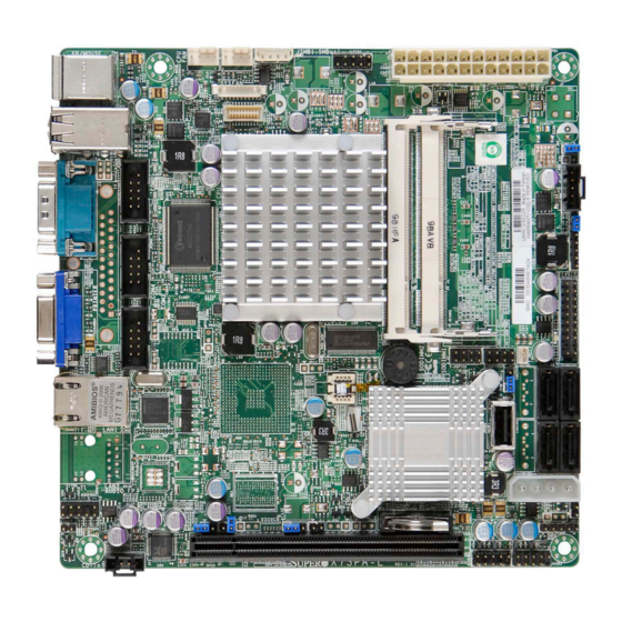
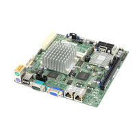
Supero SUPER X7SPA-HF Manuals
Manuals and User Guides for Supero SUPER X7SPA-HF. We have
4
Supero SUPER X7SPA-HF manuals available for free PDF download: User Manual
Supero SUPER X7SPA-HF User Manual (107 pages)
Revision 1.2a
Brand:
Supero
| Category:
Motherboard
| Size: 5.99 MB
Table of Contents
About this Manual
3
About this Motherboard
3
Manual Organization
3
Conventions Used in the Manual
4
Contacting Supermicro
5
Table of Contents
6
Chapter 1 Introduction
13
Overview
13
Checklist
13
X7SPA-L Image
14
X7SPA-H Image
15
X7SPA-HF Image
16
X7SPE-H Image
17
X7SPE-HF Image
18
X7SPE-H-D525 Image
19
X7SPE-HF-D525 Image
20
X7SPA-H-D525 Image
21
X7SPA-HF-D525 Image
22
Motherboard Layout
23
Motherboard Layout (X7SPE-H, X7SPE-HF, X7SPE-H-D525, X7SPE-HF-D525)
24
X7SPA-L, X7SPA-H, X7SPA-HF, X7SPA-H-D525, X7SPA-HF-D525 Quick Reference
25
Quick Reference
26
Ports and Connectors
27
Jumper Descriptions
28
Motherboard Features
30
X7SPA/X7SPE Series Block Diagram
33
Chipset Overview
34
I/O Controller Hub: ICH9R (X7SPA-H/X7SPA-HF, X7SPE-H/X7SPE-HF, X7SPE-H-D525, X7SPE-HF-D525, X7SPA-H-D525, X7SPA-HF-D525)
34
I/O Controller Hub: ICH9 (X7SPA-L)
34
PC Health Monitoring
35
Recovery from AC Power Loss
35
Onboard Voltage Monitoring
35
Fan Status Monitor with Software
35
CPU Overheat LED and Control
35
1-4 Power Configuration Settings
36
Slow Blinking LED for Suspend-State Indicator
36
BIOS Support for USB Keyboard
36
Main Switch Override Mechanism
36
Power Supply
36
Super I/O
37
Overview of the Nuvoton BMC Controller (X7SPA-HF/X7SPE-HF/X7SPE- HF-D525/X7SPA-HF-D525 Only)
37
LVDS (X7SPA-L Only)
38
Chapter 2 Installation
39
Static-Sensitive Devices
39
Precautions
39
Unpacking
39
Tools Needed
40
Location of Mounting Holes
40
Motherboard Installation
40
Installation Instructions
41
System Memory
42
How to Install so Dimms
42
Memory Support
42
The so DIMM Socket
43
Connectors/I/O Ports
44
Back Panel Connectors and I/O Ports
44
ATX PS/2 Keyboard and PS/2 Mouse Ports
45
Universal Serial Bus (USB)
46
Serial Ports
47
VGA Connector
48
LAN Ports / IPMI
49
Front Control Panel
50
JF1 Header Pins
50
Front Control Panel Pin Definitions
51
Hdd Led
51
NIC1/NIC2 LED Indicators
51
Power LED
51
Overheat (Oh)/Fan Fail LED
52
Power Fail LED
52
NMI Button
53
Power Button
53
Reset Button
53
Connecting Cables
54
ATX Main PWR & CPU PWR Connectors
54
External Power Connector
54
Fan Headers
55
Overheat/Fan Fail LED (JOH)
56
Front Panel Audio Header (X7SPA-L Only)
56
Chassis Intrusion
57
SATA DOM Power
57
Power SMB I C Connector
57
CD Header (X7SPA-L Only)
58
Smb
58
T-SGPIO 0/1 Headers
58
LVDS Connector (X7SPA-L Only)
59
Inverter Power Connector (X7SPA-L Only)
59
TPM Header(X7SPE-H-D525, X7SPE-HF-D525 Only)
60
Jumper Settings
61
Explanation of Jumpers
61
LAN Port Enable/Disable
62
SMB (I 2 C) Bus to PCI Slots
62
CMOS Clear
63
USB Wake-Up (Not Available on the X7SPE-H-D525, X7SPA-H-D525, X7SPA-HF-D525 and X7SPE-HF-D525)
64
TPM Support Enable (Not Available on X7SPA-H-D525, X7SPA-HF-D525, X7SPE-H-D525, X7SPE-HF-D525)
65
Watch Dog Enable/Disable
65
COM3 Redirection Select (OEM Option)
65
Power Led/Speaker
66
BMC (X7SPA-HF, X7SPE-HF, X7SPE-HF-D525, X7SPA-H-D525, X7SPA-HF-D525 Only)
66
VGA Enable
67
HDA/AC97 Select (X7SPA-L Only)
67
Power Force on Enable/Disable
68
DCD / P5V Select
68
Onboard Indicators
69
LAN Port Leds
69
Serial ATA and HDD Connections
70
SATA Connectors
70
Chapter 3 Troubleshooting
71
Troubleshooting Procedures
71
Before Power on
71
No Power
71
No Video
71
Memory Errors
72
Losing the System's Setup Configuration
72
Technical Support Procedures
72
Frequently Asked Questions
73
Returning Merchandise for Service
75
Chapter 4 BIOS
77
Introduction
77
Starting BIOS Setup Utility
77
How to Change the Configuration Data
77
How to Start the Setup Utility
78
Main Setup
78
System Overview: the Following BIOS Information will be Displayed
79
System Time/System Date
79
Processor
79
System Memory
79
4-3 Advanced Setup Configurations
80
BOOT Feature
80
Addon ROM Display Mode
80
Quick Boot
80
Quiet Boot
80
Bootup Num-Lock
81
Hit 'Del' Message Display
81
Interrupt 19 Capture
81
Power Button Function
81
PS/2 Mouse Support
81
Restore on AC Power Loss
81
Wait for 'F1' if Error
81
Watch Dog Function
81
Clock Spread Spectrum
82
CPU Configuration
82
Max CPUID Value Limit
82
Standby Power in S5
82
Execute-Disable Bit Capability (Available When Supported by the os and the CPU)
82
Hyper-Threading Technology
82
Advanced Chipset Control
83
Northbridge Configuration
83
DRAM Frequency
83
Configure DRAM Timing by SPD
83
DRAM CAS# Latency
83
DRAM RAS# to CAS# Delay
83
DRAM RAS# Precharge
83
DRAM RAS# Activate to Precharge
83
Initiate Graphics Adapter
83
Internal Graphics Mode Select
83
Video Function Configuration (X7SPA-L, X7SPE-H, X7SPA-H-D525 and X7SPE-H-D525 Only)
84
DVMT Mode Select
84
Dvmt/Fixed Memory
84
Boot Display Device
84
Alternate Video BIOS
84
Active State Power Management
84
Reserved Page Route
84
USB Functions
84
Legacy USB Support (Available if USB Functions above Is Enabled)
84
USB Controller
85
IDE/SATA Configuration
85
SATA#1 Configuration
85
SATA#2 Configuration (Available if IDE Is Enabled under "Configure SATA#1 As" Above)
85
IDE Detect Timeout (Sec)
85
Primary IDE Master/Slave,Secondary IDE Master/Slave,Third IDE Master,Fourth IDE Master
85
Pci/Pnp Configuration
87
Clear NVRAM
87
Plug & Play os
88
PCI Latency Timer
88
PCI IDE Bus Master
88
ROM Scan Ordering
88
PCI Slot 1
88
Load Onboard LAN 1 Option ROM/ Load Onboard LAN 2 Option ROM
88
Super IO Device Configuration
88
Serial Port1 Address/ Serial Port2 Address
88
Remote Access Configuration
89
Remote Access
89
Hardware Health Configuration
90
CPU Overheat Alarm
90
CPU Temperature
90
System Temperature
90
CPUFAN / SYSFAN Speed
91
CPU Vcore, AVCC, 3.3Vcc, 12V, V_DIMM, 5V, -12V, 3.3Vsb, and Vbat
92
Fan Speed Control Modes
92
ACPI Configuration
92
High Performance Event Timer
92
PS/2 KB/MS Wakeup
92
USB Device Wakeup
92
ACPI APIC Support
93
ACPI Aware O/S
93
ACPI Version Features
93
AMI OEMB Table
93
Apic Acpi Sci Irq
93
Headless Mode
93
Suspend Mode
93
IPMI Configuration (X7SPA-HF, X7SPE-HF, X7SPE-HF-D525 & X7SPA- HF-D525 Only)
93
IPMI Firmware Revision
93
Clear BMC System Event Log
94
IPMI Function
94
Set LAN Configuration
94
Status of BMC
94
View BMC System Event Log
94
BMC Watch Dog Timer Action
95
Event Log Configuration
95
Clear Event Log
95
Mark All Events as Read
95
PCIE Error Log
95
View Event Log
95
Security Settings
96
Supervisor Password
96
User Password
96
Change Supervisor Password
96
Change User Password
97
Boot Sector Virus Protection
97
Boot Settings
98
Boot Device Priority
98
Hard Disk Drives
98
Removable Drives
99
Retry Boot Devices
99
Exit Options
99
Save Changes and Exit
99
Discard Changes and Exit
100
Discard Changes
100
Load Optimal Defaults
100
Load Fail-Safe Defaults
100
Appendix A POST Error Beep Codes
101
Recoverable POST Error Beep Codes
101
Appendix B Software Installation Instructions
103
B-1 Installing Drivers
103
Configuring Supero Doctor III
104
Advertisement
Supero SUPER X7SPA-HF User Manual (107 pages)
SUPER MICRO Computer Computer Hardware User Manual
Brand:
Supero
| Category:
Motherboard
| Size: 13.43 MB
Table of Contents
About this Manual
3
About this Motherboard
3
Manual Organization
3
Conventions Used in the Manual
4
Contacting Supermicro
5
Table of Contents
6
Chapter 1 Introduction
13
Overview
13
Checklist
13
X7SPA-L Image
14
X7SPA-H Image
15
X7SPA-HF Image
16
X7SPE-H Image
17
X7SPE-HF Image
18
X7SPE-H-D525 Image
19
X7SPE-HF-D525 Image
20
X7SPA-H-D525 Image
21
X7SPA-HF-D525 Image
22
Motherboard Layout
23
Motherboard Layout (X7SPE-H, X7SPE-HF, X7SPE-H-D525, X7SPE-HF-D525)
24
X7SPA-L, X7SPA-H, X7SPA-HF, X7SPA-H-D525, X7SPA-HF-D525 Quick Reference
25
Quick Reference
26
Ports and Connectors
27
Jumper Descriptions
28
Motherboard Features
30
X7SPA/X7SPE Series Block Diagram
33
Chipset Overview
34
I/O Controller Hub: ICH9R (X7SPA-H/X7SPA-HF, X7SPE-H/X7SPE-HF, X7SPE-H-D525, X7SPE-HF-D525, X7SPA-H-D525, X7SPA-HF-D525)
34
I/O Controller Hub: ICH9 (X7SPA-L)
34
PC Health Monitoring
35
Recovery from AC Power Loss
35
Onboard Voltage Monitoring
35
Fan Status Monitor with Software
35
CPU Overheat LED and Control
35
Power Configuration Settings
36
Slow Blinking LED for Suspend-State Indicator
36
BIOS Support for USB Keyboard
36
Main Switch Override Mechanism
36
Power Supply
36
Super I/O
37
Overview of the Nuvoton BMC Controller (X7SPA-HF/X7SPE-HF/X7SPE- HF-D525/X7SPA-HF-D525 Only)
37
LVDS (X7SPA-L Only)
38
Chapter 2 Installation
39
Static-Sensitive Devices
39
Precautions
39
Unpacking
39
Tools Needed
40
Location of Mounting Holes
40
Motherboard Installation
40
Installation Instructions
41
System Memory
42
How to Install so Dimms
42
Memory Support
42
The so DIMM Socket
43
Connectors/I/O Ports
44
Back Panel Connectors and I/O Ports
44
ATX PS/2 Keyboard and PS/2 Mouse Ports
45
Universal Serial Bus (USB)
46
Serial Ports
47
VGA Connector
48
LAN Ports / IPMI
49
Front Control Panel
50
JF1 Header Pins
50
Front Control Panel Pin Definitions
51
Hdd Led
51
NIC1/NIC2 LED Indicators
51
Power LED
51
Overheat (Oh)/Fan Fail LED
52
Power Fail LED
52
NMI Button
53
Power Button
53
Reset Button
53
Connecting Cables
54
ATX Main PWR & CPU PWR Connectors
54
External Power Connector
54
Fan Headers
55
Overheat/Fan Fail LED (JOH)
56
Front Panel Audio Header (X7SPA-L Only)
56
Chassis Intrusion
57
SATA DOM Power
57
Power SMB I C Connector
57
Smb
58
T-SGPIO 0/1 Headers
58
LVDS Connector (X7SPA-L Only)
59
Inverter Power Connector (X7SPA-L Only)
59
TPM Header(X7SPE-H-D525, X7SPE-HF-D525 Only)
60
Jumper Settings
61
Explanation of Jumpers
61
LAN Port Enable/Disable
62
SMB (I 2 C) Bus to PCI Slots
62
CMOS Clear
63
USB Wake-Up (Not Available on the X7SPE-H-D525, X7SPA-H-D525, X7SPA-HF-D525 and X7SPE-HF-D525)
64
TPM Support Enable (Not Available on X7SPA-H-D525, X7SPA-HF-D525, X7SPE-H-D525, X7SPE-HF-D525)
65
Watch Dog Enable/Disable
65
COM3 Redirection Select (OEM Option)
65
Power Led/Speaker
66
BMC (X7SPA-HF, X7SPE-HF, X7SPE-HF-D525, X7SPA-H-D525, X7SPA-HF-D525 Only)
66
VGA Enable
67
HDA/AC97 Select (X7SPA-L Only)
67
Power Force on Enable/Disable
68
DCD / P5V Select
68
Onboard Indicators
69
LAN Port Leds
69
Serial ATA and HDD Connections
70
SATA Connectors
70
Chapter 3 Troubleshooting
71
Troubleshooting Procedures
71
Before Power on
71
No Power
71
No Video
71
Memory Errors
72
Losing the System's Setup Configuration
72
Technical Support Procedures
72
Frequently Asked Questions
73
Returning Merchandise for Service
75
Chapter 4 BIOS
77
Introduction
77
Starting BIOS Setup Utility
77
How to Change the Configuration Data
77
How to Start the Setup Utility
78
Main Setup
78
System Overview: the Following BIOS Information will be Displayed
79
System Time/System Date
79
Processor
79
System Memory
79
Advanced Setup Configurations
80
BOOT Feature
80
Addon ROM Display Mode
80
Quick Boot
80
Quiet Boot
80
Bootup Num-Lock
81
Hit 'Del' Message Display
81
Interrupt 19 Capture
81
Power Button Function
81
PS/2 Mouse Support
81
Restore on AC Power Loss
81
Wait for 'F1' if Error
81
Watch Dog Function
81
Clock Spread Spectrum
82
CPU Configuration
82
Max CPUID Value Limit
82
Standby Power in S5
82
Execute-Disable Bit Capability (Available When Supported by the os and the CPU)
82
Hyper-Threading Technology
82
Advanced Chipset Control
83
Northbridge Configuration
83
DRAM Frequency
83
Configure DRAM Timing by SPD
83
DRAM CAS# Latency
83
DRAM RAS# to CAS# Delay
83
DRAM RAS# Precharge
83
DRAM RAS# Activate to Precharge
83
Initiate Graphics Adapter
83
Internal Graphics Mode Select
83
Video Function Configuration (X7SPA-L, X7SPE-H, X7SPA-H-D525 and X7SPE-H-D525 Only)
84
DVMT Mode Select
84
Dvmt/Fixed Memory
84
Boot Display Device
84
Alternate Video BIOS
84
Active State Power Management
84
Reserved Page Route
84
USB Functions
84
Legacy USB Support (Available if USB Functions above Is Enabled)
84
USB Controller
85
IDE/SATA Configuration
85
SATA#1 Configuration
85
SATA#2 Configuration (Available if IDE Is Enabled under "Configure SATA#1 As" Above)
85
IDE Detect Timeout (Sec)
85
Primary IDE Master/Slave,Secondary IDE Master/Slave,Third IDE Master,Fourth IDE Master
85
Pci/Pnp Configuration
87
Clear NVRAM
87
Plug & Play os
88
PCI Latency Timer
88
PCI IDE Bus Master
88
ROM Scan Ordering
88
PCI Slot 1
88
Load Onboard LAN 1 Option ROM/ Load Onboard LAN 2 Option ROM
88
Super IO Device Configuration
88
Serial Port1 Address/ Serial Port2 Address
88
Remote Access Configuration
89
Remote Access
89
Hardware Health Configuration
90
CPU Overheat Alarm
90
CPU Temperature
90
System Temperature
90
CPUFAN / SYSFAN Speed
91
CPU Vcore, AVCC, 3.3Vcc, 12V, V_DIMM, 5V, -12V, 3.3Vsb, and Vbat
92
Fan Speed Control Modes
92
ACPI Configuration
92
High Performance Event Timer
92
PS/2 KB/MS Wakeup
92
USB Device Wakeup
92
ACPI APIC Support
93
ACPI Aware O/S
93
ACPI Version Features
93
AMI OEMB Table
93
Apic Acpi Sci Irq
93
Headless Mode
93
Suspend Mode
93
IPMI Configuration (X7SPA-HF, X7SPE-HF, X7SPE-HF-D525 & X7SPA- HF-D525 Only)
93
IPMI Firmware Revision
93
Clear BMC System Event Log
94
IPMI Function
94
Set LAN Configuration
94
Status of BMC
94
View BMC System Event Log
94
BMC Watch Dog Timer Action
95
Event Log Configuration
95
Clear Event Log
95
Mark All Events as Read
95
PCIE Error Log
95
View Event Log
95
Security Settings
96
Supervisor Password
96
User Password
96
Change Supervisor Password
96
Change User Password
97
Boot Sector Virus Protection
97
Boot Settings
98
Boot Device Priority
98
Hard Disk Drives
98
Removable Drives
99
Retry Boot Devices
99
Exit Options
99
Save Changes and Exit
99
Discard Changes and Exit
100
Discard Changes
100
Load Optimal Defaults
100
Load Fail-Safe Defaults
100
Appendix A POST Error Beep Codes
101
Recoverable POST Error Beep Codes
101
Appendix B Software Installation Instructions
103
B-1 Installing Drivers
103
Configuring Supero Doctor III
104
Supero SUPER X7SPA-HF User Manual (107 pages)
Brand:
Supero
| Category:
Motherboard
| Size: 13.43 MB
Table of Contents
About this Motherboard
3
Manual Organization
3
Conventions Used in the Manual
4
Contacting Supermicro
5
Table of Contents
6
Chapter 1 Introduction
13
Overview
13
Checklist
13
X7SPA-L Image
14
X7SPA-H Image
15
X7SPA-HF Image
16
X7SPE-H Image
17
X7SPE-HF Image
18
X7SPE-H-D525 Image
19
X7SPE-HF-D525 Image
20
X7SPA-H-D525 Image
21
X7SPA-HF-D525 Image
22
Motherboard Layout
23
Motherboard Layout (X7SPE-H, X7SPE-HF, X7SPE-H-D525, X7SPE-HF-D525)
24
X7SPA-L, X7SPA-H, X7SPA-HF, X7SPA-H-D525, X7SPA-HF-D525 Quick Reference
25
Motherboard Features
30
X7SPA/X7SPE Series Block Diagram
33
Chipset Overview
34
I/O Controller Hub: ICH9R (X7SPA-H/X7SPA-HF, X7SPE-H/X7SPE-HF, X7SPE-H-D525, X7SPE-HF-D525, X7SPA-H-D525, X7SPA-HF-D525)
34
I/O Controller Hub: ICH9 (X7SPA-L)
34
PC Health Monitoring
35
Recovery from AC Power Loss
35
Onboard Voltage Monitoring
35
Fan Status Monitor with Software
35
CPU Overheat LED and Control
35
Power Configuration Settings
36
Slow Blinking LED for Suspend-State Indicator
36
BIOS Support for USB Keyboard
36
Main Switch Override Mechanism
36
Power Supply
36
Super I/O
37
Overview of the Nuvoton BMC Controller (X7SPA-HF/X7SPE-HF/X7SPE- HF-D525/X7SPA-HF-D525 Only)
37
LVDS (X7SPA-L Only)
38
Static-Sensitive Devices
39
Precautions
39
Unpacking
39
Tools Needed
40
Location of Mounting Holes
40
Motherboard Installation
40
Installation Instructions
41
System Memory
42
How to Install so Dimms
42
Memory Support
42
The so DIMM Socket
43
Connectors/I/O Ports
44
Back Panel Connectors and I/O Ports
44
Universal Serial Bus (USB)
46
Serial Ports
47
VGA Connector
48
LAN Ports / IPMI
49
Front Control Panel
50
JF1 Header Pins
50
Front Control Panel Pin Definitions
51
Power LED
51
Hdd Led
51
NIC1/NIC2 LED Indicators
51
Overheat (Oh)/Fan Fail LED
52
Power Fail LED
52
Reset Button
53
Power Button
53
NMI Button
53
Connecting Cables
54
ATX Main PWR & CPU PWR Connectors
54
External Power Connector
54
Fan Headers
55
Overheat/Fan Fail LED (JOH)
56
Front Panel Audio Header (X7SPA-L Only)
56
Chassis Intrusion
57
SATA DOM Power
57
Power SMB I C Connector
57
Smb
58
T-SGPIO 0/1 Headers
58
LVDS Connector (X7SPA-L Only)
59
Inverter Power Connector (X7SPA-L Only)
59
TPM Header(X7SPE-H-D525, X7SPE-HF-D525 Only)
60
Jumper Settings
61
Explanation of Jumpers
61
LAN Port Enable/Disable
62
SMB (I 2 C) Bus to PCI Slots
62
CMOS Clear
63
USB Wake-Up (Not Available on the X7SPE-H-D525, X7SPA-H-D525, X7SPA-HF-D525 and X7SPE-HF-D525)
64
TPM Support Enable (Not Available on X7SPA-H-D525, X7SPA-HF-D525, X7SPE-H-D525, X7SPE-HF-D525)
65
Watch Dog Enable/Disable
65
COM3 Redirection Select (OEM Option)
65
Power Led/Speaker
66
BMC (X7SPA-HF, X7SPE-HF, X7SPE-HF-D525, X7SPA-H-D525, X7SPA-HF-D525 Only)
66
VGA Enable
67
HDA/AC97 Select (X7SPA-L Only)
67
Power Force on Enable/Disable
68
DCD / P5V Select
68
Onboard Indicators
69
LAN Port Leds
69
Serial ATA and HDD Connections
70
SATA Connectors
70
Chapter 3 Troubleshooting
71
Troubleshooting Procedures
71
Before Power on
71
No Power
71
No Video
71
Memory Errors
72
Losing the System's Setup Configuration
72
Technical Support Procedures
72
Frequently Asked Questions
73
Returning Merchandise for Service
75
Chapter 4 BIOS
77
Introduction
77
Starting BIOS Setup Utility
77
How to Change the Configuration Data
77
How to Start the Setup Utility
78
Main Setup
78
System Overview: the Following BIOS Information will be Displayed
79
System Time/System Date
79
Processor
79
System Memory
79
Advanced Setup Configurations
80
BOOT Feature
80
Quick Boot
80
Quiet Boot
80
Addon ROM Display Mode
80
Bootup Num-Lock
81
PS/2 Mouse Support
81
Wait for 'F1' if Error
81
Hit 'Del' Message Display
81
Watch Dog Function
81
Power Button Function
81
Restore on AC Power Loss
81
Interrupt 19 Capture
81
Standby Power in S5
82
CPU Configuration
82
Clock Spread Spectrum
82
Max CPUID Value Limit
82
Execute-Disable Bit Capability (Available When Supported by the os and the CPU)
82
Hyper-Threading Technology
82
Advanced Chipset Control
83
Northbridge Configuration
83
DRAM Frequency
83
Configure DRAM Timing by SPD
83
DRAM CAS# Latency
83
DRAM RAS# to CAS# Delay
83
DRAM RAS# Precharge
83
DRAM RAS# Activate to Precharge
83
Initiate Graphics Adapter
83
Internal Graphics Mode Select
83
Video Function Configuration (X7SPA-L, X7SPE-H, X7SPA-H-D525 and X7SPE-H-D525 Only)
84
DVMT Mode Select
84
Dvmt/Fixed Memory
84
Boot Display Device
84
Alternate Video BIOS
84
Active State Power Management
84
Reserved Page Route
84
USB Functions
84
Legacy USB Support (Available if USB Functions above Is Enabled)
84
USB Controller
85
IDE/SATA Configuration
85
SATA#1 Configuration
85
SATA#2 Configuration (Available if IDE Is Enabled under "Configure SATA#1 As" Above)
85
IDE Detect Timeout (Sec)
85
Primary IDE Master/Slave,Secondary IDE Master/Slave,Third IDE Master,Fourth IDE Master
85
Pci/Pnp Configuration
87
Clear NVRAM
87
Plug & Play os
88
PCI Latency Timer
88
PCI IDE Bus Master
88
ROM Scan Ordering
88
PCI Slot 1
88
Load Onboard LAN 1 Option ROM/ Load Onboard LAN 2 Option ROM
88
Super IO Device Configuration
88
Serial Port1 Address/ Serial Port2 Address
88
Remote Access Configuration
89
Remote Access
89
Hardware Health Configuration
90
CPU Overheat Alarm
90
CPU Temperature
90
System Temperature
90
CPUFAN / SYSFAN Speed
91
Fan Speed Control Modes
92
CPU Vcore, AVCC, 3.3Vcc, 12V, V_DIMM, 5V, -12V, 3.3Vsb, and Vbat
92
ACPI Configuration
92
High Performance Event Timer
92
USB Device Wakeup
92
PS/2 KB/MS Wakeup
92
ACPI Aware O/S
93
Suspend Mode
93
AMI OEMB Table
93
ACPI APIC Support
93
Apic Acpi Sci Irq
93
Headless Mode
93
ACPI Version Features
93
IPMI Configuration (X7SPA-HF, X7SPE-HF, X7SPE-HF-D525 & X7SPA- HF-D525 Only)
93
IPMI Firmware Revision
93
Status of BMC
94
IPMI Function
94
View BMC System Event Log
94
Clear BMC System Event Log
94
Set LAN Configuration
94
BMC Watch Dog Timer Action
95
Event Log Configuration
95
View Event Log
95
Mark All Events as Read
95
Clear Event Log
95
PCIE Error Log
95
Security Settings
96
Supervisor Password
96
User Password
96
Change Supervisor Password
96
Change User Password
97
Boot Sector Virus Protection
97
Boot Settings
98
Boot Device Priority
98
Hard Disk Drives
98
Removable Drives
99
Retry Boot Devices
99
Exit Options
99
Save Changes and Exit
99
Discard Changes and Exit
100
Discard Changes
100
Load Optimal Defaults
100
Load Fail-Safe Defaults
100
Appendix A POST Error Beep Codes
101
Recoverable POST Error Beep Codes
101
Appendix B Software Installation Instructions
103
B-1 Installing Drivers
103
Configuring Supero Doctor III
104
Advertisement
Supero SUPER X7SPA-HF User Manual (93 pages)
Brand:
Supero
| Category:
Motherboard
| Size: 5.61 MB
Table of Contents
About this Manual
3
About this Motherboard
3
Manual Organization
3
Conventions Used in the Manual
4
Contacting Supermicro
5
Table of Contents
6
Chapter 1 Introduction
10
Overview
10
Checklist
10
X7SPA-L Image
11
X7SPA-H Image
12
X7SPA-HF Image
13
Motherboard Layout
14
X7SPA-L/X7SPA-H/X7SPA-HF Quick Reference
15
Motherboard Features
18
X7SPA Series Block Diagram
20
Chipset Overview
21
I/O Controller Hub: ICH9R (X7SPA-H & X7SPA-HF)
21
I/O Controller Hub: ICH9 (X7SPA-L)
21
PC Health Monitoring
22
Recovery from AC Power Loss
22
Onboard Voltage Monitoring
22
Fan Status Monitor with Software
22
CPU Overheat LED and Control
22
1-4 Power Configuration Settings
23
Slow Blinking LED for Suspend-State Indicator
23
BIOS Support for USB Keyboard
23
Main Switch Override Mechanism
23
Power Supply
23
Super I/O
24
Overview of the Nuvoton BMC Controller (X7SPA-HF Only)
24
LVDS (X7SPA-L Only)
25
Chapter 2 Installation
26
Static-Sensitive Devices
26
Precautions
26
Unpacking
26
Tools Needed
27
Location of Mounting Holes
27
Motherboard Installation
27
Installation Instructions
28
System Memory
29
How to Install so Dimms
29
Memory Support
29
The so DIMM Socket
30
Connectors/I/O Ports
31
Back Panel Connectors and I/O Ports
31
Back Panel Connectors
32
Universal Serial Bus (USB)
33
Serial Ports
34
VGA Connector
35
LAN Ports / IPMI (X7SPA-HF)
36
Front Control Panel
37
JF1 Header Pins
37
Front Control Panel Pin Definitions
38
Power LED
38
Hdd Led
38
NIC1/NIC2 LED Indicators
38
Overheat (Oh)/Fan Fail LED
39
Power Fail LED
39
Reset Button
40
Power Button
40
NMI Button
40
Connecting Cables
41
ATX Main PWR & CPU PWR Connectors
41
External Power Connector
41
Fan Headers
42
Overheat/Fan Fail LED (JOH)
43
Front Panel Audio Header
43
Chassis Intrusion
44
SATA DOM Power
44
Power SMB I C Connector
44
CD Header
45
Smb
45
T-SGPIO 0/1 Headers
45
LVDS Connector
46
Inverter Power Connector
46
Jumper Settings
47
Explanation of Jumpers
47
LAN Port Enable/Disable
48
SMB (I 2 C) Bus to PCI Slots
48
CMOS Clear
49
USB Wake-Up
50
TPM Support Enable
51
Watch Dog Enable/Disable
51
COM3 Redirection Select
51
Power Led/Speaker
52
BMC (X7SPA-HF Only)
52
VGA Enable
53
HDA/AC97 Select
53
Power Force on Enable/Disable
54
DCD / P5V Select
54
Onboard Indicators
55
LAN Port Leds
55
Serial ATA and HDD Connections
56
SATA Connectors
56
Chapter 3 Troubleshooting
58
Troubleshooting Procedures
58
Before Power on
58
No Power
58
No Video
58
Memory Errors
59
Losing the System's Setup Configuration
59
Technical Support Procedures
59
Frequently Asked Questions
60
Returning Merchandise for Service
62
Chapter 4 BIOS
64
Introduction
64
Starting BIOS Setup Utility
64
How to Change the Configuration Data
64
How to Start the Setup Utility
65
Main Setup
65
4-3 Advanced Setup Configurations
67
Boot Feature
67
Advanced Chipset Control
70
Hardware Health Configuration
77
Security Settings
83
Boot Settings
85
Boot Device Priority
85
Hard Disk Drives
85
Removable Drives
86
Exit Options
86
Appendix A POST Error Beep Codes
88
Recoverable POST Error Beep Codes
88
Appendix B Software Installation Instructions
90
B-1 Installing Drivers
90
Configuring Supero Doctor III
91
Advertisement
Related Products
Supero SUPER X7SPA-H
Supero SUPER X7SPE-HF
Supero SUPER X7SPE-H
Supero SUPER X7SPA-L
Supero X7SPE-H-D525
Supero X7SPE-HF-D525
Supero X7SPA-H-D525
Supero X7SPA-HF-D525
Supero X7SBA
Supero Supero X7SBL-LN1/LN2
Supero Categories
Motherboard
Server
Chassis
Computer Hardware
Desktop
More Supero Manuals
Login
Sign In
OR
Sign in with Facebook
Sign in with Google
Upload manual
Upload from disk
Upload from URL