Sign In
Upload
Manuals
Brands
Supermicro Manuals
Network Hardware
SuperBlade SBI-7125C-T3
Supermicro SuperBlade SBI-7125C-T3 Manuals
Manuals and User Guides for Supermicro SuperBlade SBI-7125C-T3. We have
2
Supermicro SuperBlade SBI-7125C-T3 manuals available for free PDF download: User Manual
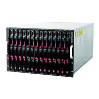
Supermicro SuperBlade SBI-7125C-T3 User Manual (84 pages)
Brand:
Supermicro
| Category:
Network Storage Server
| Size: 10.01 MB
Table of Contents
About this Manual
3
Table of Contents
5
Chapter 1 Introduction
13
Overview
13
Quick Start Setup
13
Officeblade and Datacenterblade Systems
14
Datacenterblade
14
Officeblade
15
Twin Blades
15
Software Mode Selection
15
Product Checklist of Typical Components
16
Blade Enclosure Features
17
Table 1-1. Superblade Enclosures
17
Table 1-2. Number of Network Modules that May be Installed in each Enclosure
19
Enclosure Cooling
20
Leds
20
Middle Plane
20
Power
20
Power Supply Features
21
Power Supply Modules
21
Power Cord
21
Power Supply Failure
22
Special Design Features
22
Operating System Support
22
Remote Management
22
Computing Density/Power
22
High-Efficiency Power Supplies
23
Returning Merchandise for Service
23
Contacting Supermicro
24
Chapter 2 System Safety
25
Electrical Safety Precautions
25
General Safety Precautions
26
Electrostatic Discharge Precautions
26
Operating Precautions
27
Chapter 3 Setup and Installation
29
Overview
29
Unpacking the System
29
Choosing a Setup Location
29
Rack Precautions
30
Server Precautions
30
Rack Mounting Considerations
30
Ambient Operating Temperature
30
Reduced Airflow
30
Mechanical Loading
31
Circuit Overloading
31
Reliable Ground
31
Installing the System into a Rack
31
Rack Mounting Hardware
31
Installation
32
Figure 3-1. Positioning the Enclosure Template
32
Figure 3-2. Securing the Rails to the Rack
32
Figure 3-3. Attaching the Optional Handles
33
Figure 3-4. Enclosure Installed into Rack
34
Chapter 4 System Modules
35
Figure 4-1. Typical Blade System Module Configuration: Rear View
35
Table 4-1. Typical Blade System Module Configuration: Rear View
35
Chassis Management Module
36
Figure 4-2. Chassis Management Module
37
Table 4-2. CMM Module Interface
37
Table 4-3. CMM Module Features
37
Module Redundancy
38
Master/Slave Modules
38
SBM-CMM-001 or SBM-CMM-003 Module Installation
38
BMB-CMM-002 Module Installation
39
Figure 4-3. Stand-Off Screw Holes on Module Board
39
Figure 4-4. Mini-CMM Mounted on Module Board
40
Configuring the CMM
41
Figure 4-5. Choose Internal Protocol
41
Figure 4-6. Manually Configure the IP Address
42
CMM Functions
43
Figure 4-7. Changing Settings
43
Local KVM
44
Monitoring Functions
44
Remote KVM over IP
44
Remote Storage (Virtual Media)
44
Serial over LAN (SOL)
44
Power Consumption Management
45
CMM Switches and Buttons
45
USB Switch
45
Figure 4-8. USB Switch on Rear of CMM
45
Reset Button
46
Firmware
46
Web-Based Management Utility
46
Table 4-4. CMM Reset Settings
46
Address Defaults
47
Network Connection/Login
47
Supported Browsers
47
Table 4-5. Address Defaults
47
Figure 4-9. Home Page
48
Home Page
48
Table 4-6. Home Page Controls
48
Double-Wide and Triple-Wide Modules
49
Setting up a Double-Wide Bay
49
Figure 4-10. Horizontal Spacers for Single Bays
50
Figure 4-11. Modifying for a Double-Wide Module Bay (Steps 1 & 2)
51
Figure 4-12. Modifying for a Double-Wide Module Bay (Steps 3 & 4)
52
Figure 4-13. Modifying for an Upper Left Double-Wide Bay (Step 1)
53
Figure 4-14. Modifying for an Upper Left Double-Wide Bay (Step 3)
54
Figure 4-15. Modifying for an Upper Left Double-Wide Bay (Step 4)
55
Figure 4-16. Modifying for an Upper Left Double-Wide Bay (Step 5)
56
Figure 4-17. Modifying for an Upper Left Double-Wide Bay (Step 6)
57
Setting up a Triple Wide Bay
58
Figure 4-18. Modifying for a Triple Wide Bay (Step 1 & 2)
58
Figure 4-19. Modifying for a Triple Wide Bay (Step 3 & 4)
59
Figure 4-20. Modifying for a Triple Wide Bay (Step 5)
60
Figure 4-21. Modifying for a Triple Wide Bay (Step 6)
61
Chapter 5 Power Supply Modules
63
Power Supply Modules
63
Figure 5-1. PWS-1K41-BR Power Supply
64
Table 5-1. PWS-1K41-BR Power Supply Features
64
Figure 5-2. PWS-1K62-BR Power Supply
65
Table 5-2. PWS-1K62-BR Power Supply Features
65
Figure 5-3. PWS-2K01-BR Power Supply
66
Table 5-3. PWS-2K01-BR Power Supply Features
66
Figure 5-4. PWS-2K53-BR Power Supply
67
Table 5-4. PWS-2K53-BR Power Supply Features
67
Installing a Power Supply
68
Power Supply Failure
68
Removing a Power Supply
68
Power Supply Fans
69
Figure 5-5. Power Supply Module
69
Power Components
70
Power Cord
70
Figure 5-6. Power Components
70
Table 5-5. Power Components
70
Power Cord Tie and Clamp
71
Figure 5-7. Power Cord Tie and Clamp Parts
71
Figure 5-8. Power Cord Tie and Clamp Assembly
72
Appendix A System Specifications
73
Enclosure Specifications
73
Table A-1. Enclosure Specification Features
73
Environmental Specifications
74
Address Defaults
74
Table A-2. Environmental Specification Features
74
Table A-3. Address Defaults
74
Power Supply Power Calculations
75
Table A-4. Power Supply: Power Calculations (PWS-2K53-BR
75
Table A-5. Power Supply: Power Calculations (PWS-2K01-BR
75
Table A-6. Power Supply: Power Calculations (PWS-1K62-BR
76
Table A-7. Power Supply: Power Calculations (PWS-1K41-BR
76
Appendix Bled Descriptions
77
Gigabit Ethernet Module LED Descriptions
77
Table B-1. Gigabit Ethernet Switch LED Indicators
77
1/10 Gigabit Ethernet Module LED Descriptions
78
Table B-2. 1/10 Gigabit Ethernet Switch LED Indicators
78
Table B-3. Stacking LED Activity (SBM-GEM-X2C/+ Only
78
SBM-XEM-X10SM 10G Ethernet Switch LED Descriptions
79
Table B-4. SBM-XEM-X10SM Ethernet Switch Leds
79
SBM-IBS-001 Infiniband Switch LED Descriptions
80
Table B-5. SBM-IBS-001 Infiniband Switch Leds
80
SBM-IBS-Q3616M and SBM-IBS-Q3618M Infiniband Switch LED Descriptions
81
Table B-6. SBM-IBS-Q3616M and SBM-IBS-Q3618M Infiniband Switch Leds
81
Advertisement
Supermicro SuperBlade SBI-7125C-T3 User Manual (80 pages)
Blade Module
Brand:
Supermicro
| Category:
Network Hardware
| Size: 3.09 MB
Table of Contents
About this Manual
3
Table of Contents
5
Chapter 1 Introduction
13
Overview
13
Product Checklist of Typical Components
13
Blade Module Features
14
Processors
14
Memory
14
Table 1-1. SBI-7125C-T3 Blade Specification Features
14
Storage
15
Density
15
Figure 1-1. Full Rack of Blade Enclosures and Blade Servers
15
Contacting Supermicro
16
Chapter 2 System Safety
17
Electrical Safety Precautions
17
General Safety Precautions
18
Electrostatic Discharge Precautions
18
Operating Precautions
18
Chapter 3 Setup and Installation
19
Overview
19
Installing Blade Modules
19
Powering up a Blade Unit
19
Powering down a Blade Unit
19
Removing a Blade Unit from the Enclosure
19
Removing/Replacing the Blade Cover
20
Installing a Blade Unit into the Enclosure
20
Figure 3-1. Inserting a Blade into the Enclosure
21
Figure 3-2. Locking the Blade into Position
21
Processor Installation
22
Onboard Battery Installation
23
Figure 3-3. Installing a Processor in a Socket
23
Memory Installation
24
Populating Memory Slots
24
Figure 3-4. Installing the Onboard Battery
24
Table 3-1. Populating Six Memory Slots for Interleaved Operation
24
DIMM Installation
25
Figure 3-5. 6-Slot DIMM Numbering
25
Hard Disk Drive Installation
26
Figure 3-6. Installing a DIMM into a Memory Slot
26
Installing the Operating System
27
Figure 3-7. Installing a Hard Drive in a Carrier
27
Installing Via PXE Boot
28
Installing Via Virtual Media (Drive Redirection)
28
Installing with an External USB CD-ROM Drive
28
Management Software
29
Configuring and Setting up RAID
29
Chapter 4 Blade Module Features
31
Figure 4-1. SBI-7125C-T3 Blade Unit Front View
31
Table 4-1. SBI-7125C-T3 Blade Unit Features
31
Control Panel
32
Figure 4-2. Blade Control Panel
32
Table 4-2. Blade Control Panel
32
KVM Button
33
KVM Connector
33
LED Indicators
33
Power Button
33
Table 4-3. Blade Module LED Indicators
33
Figure 4-3. B7DCL Mainboard
34
Mainboard
34
Figure 4-4. Intel 5100/Intel ICH9R Chipset: Block Diagram
35
Table 4-4. B7DCL Mainboard Layout
35
CMOS Clear
36
Jumpers
36
Blade Unit Components
36
Figure 4-5. Exploded View of a SBI-7125C-T3 Blade Module
36
Hard Disk Drives
37
Memory Support
37
Table 4-5. Main Components of a SBI-7125C-T3 Blade Module
37
Chapter 5 RAID Setup Procedure
39
RAID Configurations
39
Preparing for Setup
39
RAID Software
39
Chapter 6 BIOS
41
Introduction
41
System BIOS
41
How to Change the Configuration Data
41
Starting the Setup Utility
41
BIOS Updates
42
Flashing BIOS
42
Running Setup
43
Main BIOS Setup
44
Figure 6-1. Main BIOS Setup Menu
44
Table 6-1. Main BIOS Setup Menu Options
44
Advanced Setup
45
Figure 6-2. Advanced Setup Menu
45
Table 6-2. Advanced Setup Menu Options
45
Boot Features Submenu
47
Figure 7. Boot Features Submenu
47
Table 6-3. Boot Features Submenu Menu Options
47
Figure 6-1. Memory Cache Submenu
48
Memory Cache Submenu
48
Table 6-4. Memory Cache Submenu Menu Options
49
Figure 6-2. PCI Configuration Submenu
50
PCI Configuration Submenu
50
Table 6-5. PCI Configuration Submenu Menu Options
50
Advanced Chipset Control Submenu
51
Figure 6-3. Advanced Chipset Control Submenu
51
Table 6-6. Advanced Chipset Control Submenu Menu Options
51
Advanced Processor Options Submenu
52
Figure 6-4. Advanced Processor Options Submenu
52
Table 6-7. Advanced Processor Options Submenu Menu Options
53
Figure 6-5. I/O Device Configuration Submenu
54
I/O Device Configuration Submenu
54
Table 6-8. I/O Device Configuration Submenu Menu Options
54
DMI Event Logging Submenu
55
Figure 6-6. DMI Event Logging Submenu
55
Table 6-9. DMI Event Logging Submenu Menu Options
55
Console Redirection Submenu
56
Figure 6-7. Console Redirection Submenu
56
Figure 6-8. Hardware Monitor Submenu
57
Hardware Monitor Submenu
57
Table 6-10. Console Redirection Submenu Menu Options
57
Table 6-11. Hardware Monitor Submenu Menu Options
58
IPMI Submenu
59
Table 6-12. IPMI Submenu Menu Options
59
Security
60
Figure 6-9. Security Menu
60
Table 6-13. Security Menu Options
60
Boot
61
Figure 6-10. Boot Menu
61
Boot Priority Order/Excluded from Boot Order
62
Exit
62
Figure 6-11. Exit Menu
62
Table 6-14. Exit Menu Options
63
Appendix Abios POST Codes
65
BIOS POST Messages
65
Table A-1. BIOS POST Messages
65
A-2 BIOS POST Codes
67
Recoverable POST Errors
68
Terminal POST Errors
68
Table A-2. Terminal POST Errors
68
Table A-3. Boot Block Flash ROM Terminal POST Errors
72
Appendix B Iscsi Setup Procedure
75
Figure B-1. Microsoft MPIO Multipathing Support for Iscsi Check Box
76
Figure B-2. Configure Iscsi Network Boot Support Check Box
77
Advertisement
Related Products
Supermicro SBI-7126T-T1E
Supermicro SBI-7126T-T1L
Supermicro SuperBlade SBI-7425C-S3
Supermicro SBI-7425C-S3E
Supermicro SBA-7121M-T1
Supermicro Supero SC842TQ-865B
Supermicro SC836 X9
Supermicro SuperServer SYS-E100-12T-H
Supermicro SuperServer SYS-E100-12T-E
Supermicro SuperServer SYS-E100-12T-C
Supermicro Categories
Server
Motherboard
Computer Hardware
Chassis
Switch
More Supermicro Manuals
Login
Sign In
OR
Sign in with Facebook
Sign in with Google
Upload manual
Upload from disk
Upload from URL