Sign In
Upload
Manuals
Brands
SMC Networks Manuals
Switch
GS24C-SMART
SMC Networks GS24C-SMART Manuals
Manuals and User Guides for SMC Networks GS24C-SMART. We have
2
SMC Networks GS24C-SMART manuals available for free PDF download: Quick Installation Manual, User Manual
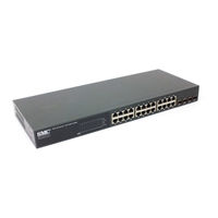
SMC Networks GS24C-SMART Quick Installation Manual (122 pages)
Managed Ethernet Switch
Brand:
SMC Networks
| Category:
Switch
| Size: 2.27 MB
Table of Contents
Installation Guide
3
Japan VCCI Class a
7
Power Cord Safety
9
Safety Compliance
9
Warnings and Cautionary Messages
13
End of Product Life Span
14
Manufacturing Materials
14
Related Publications
14
Table of Contents
15
Figure 1-1 Front Panels
23
Figure 1-2 Rear Panel
23
About the EZ Switch 10/100/1000
24
Switch Architecture
24
Network Management Options
24
Description of Hardware
25
10/100/1000BASE-T Ports
25
SFP Slots
25
Port and Power Status Leds
25
Power Supply Socket
26
Table 1-1 Port Status Leds
26
Table 1-2 Power Status LED
26
Figure 1-3 Port Leds and Power LED
26
Features and Benefits
27
Connectivity
27
Figure 1-4 Power Supply Socket
27
Expandability
28
Performance
28
Management
28
Network Planning
29
Introduction to Switching
29
Application Examples
30
Collapsed Backbone
30
Figure 2-1 Collapsed Backbone
30
Central Wiring Closet
31
Figure 2-2 Central Wiring Closet
31
Remote Connections with Fiber Cable
32
Figure 2-3 Remote Connections with Fiber Cable
32
Making VLAN Connections
33
Figure 2-4 Making VLAN Connections
33
Application Notes
34
Installing the Switch
35
Selecting a Site
35
Ethernet Cabling
36
Figure 3-1 RJ-45 Connections
36
Equipment Checklist
37
Package Contents
37
Optional Rack-Mounting Equipment
37
Mounting
37
Rack Mounting
38
Figure 3-2 Attaching the Brackets
39
Figure 3-3 Installing the Switch in a Rack
39
Desktop or Shelf Mounting
40
Figure 3-4 Attaching the Adhesive Feet
40
Installing an Optional SFP Transceiver into the Switch
41
Table 3-1 Optional Transcievers
41
Figure 3-5 Inserting an SFP Transceiver into a Slot
41
Connecting to a Power Source
42
Figure 3-6 Power Socket
42
Making Network Connections
43
Connecting Network Devices
43
Twisted-Pair Devices
43
Cabling Guidelines
43
Connecting to Pcs, Servers, Hubs and Switches
44
Figure 4-1 Making Twisted-Pair Connections
44
Network Wiring Connections
45
Figure 4-2 Wiring Closet Connections
45
Fiber Optic SFP Devices
46
Figure 4-3 Making Connections to SFP Transceivers
47
Connectivity Rules
48
1000BASE-T Cable Requirements
48
1000 Mbps Gigabit Ethernet Collision Domain
48
Table 4-1 Maximum 1000BASE-T Gigabit Ethernet Cable Length
48
Table 4-2 Maximum 1000BASE-SX Fiber Optic Cable Length
48
Mbps Fast Ethernet Collision Domainn
49
10 Mbps Ethernet Collision Domain
49
Table 4-3 Maximum 1000BASE-LX Fiber Optic Cable Length
49
Table 4-4 Maximum 1000BASE-ZX Fiber Optic Cable Length
49
Table 4-5 Maximum Fast Ethernet Cable Length
49
Table 4-6 Maximum Ethernet Cable Length
49
Cable Labeling and Connection Records
50
Configuring the Switch
51
Using the Web Interface
51
Navigating the Web Browser Interface
52
Home Page
52
Figure 5-1 Home Page
52
Configuration Options
53
Panel Display
53
Table 5-1 Web Page Configuration Buttons
53
Figure 5-2 Front Panel Indicators
53
Main Menu
54
Table 5-2 Switch Main Menu
54
Web Configuration
56
Displaying Status Overview
56
Figure 5-3 Switch Information
58
Showing Port Statistics
59
Table 5-3 Port Statistics
59
Displaying System Name
62
Figure 5-4 Port Statistics
62
Setting the Switch's IP Address
63
Figure 5-5 System Name
63
Configuring the Logon Password
64
Figure 5-6 LAN Settings
64
Tools
65
Figure 5-7 Password Settings
65
Figure 5-8 Reset to Factory Defaults
66
Figure 5-9 Upgrade Firmware
66
Figure 5-10 Restart Switch
67
Register Product
68
Static MAC
68
Figure 5-11 Register Product
68
Counter Config
69
Figure 5-12 Static MAC Address Configuration
69
Port Configuration
70
Figure 5-13 Counter Configuration
70
Configuring Rate Limits
71
Figure 5-14 Port Configuration
71
Figure 5-15 Rate Limiting
72
Storm Control
73
Port Mirroring
74
Figure 5-16 Port Broadcast Control
74
Cable Diagnostic
75
Figure 5-17 Port Mirroring
75
Trunks Membership
76
Figure 5-18 Cable Diagnostics
76
Trunk Configuration
77
Figure 5-19 Trunk Membership
77
Trunk Rate Limit
78
Figure 5-20 Trunk Configuration
78
VLAN Settings
79
Figure 5-21 Trunk Rate Limiting
79
QOS Settings
82
Security
84
Figure 5-26
88
IGMP Snoop
89
IGMP Snoop
91
Troubleshooting
93
Diagnosing Switch Indicators
93
Table A-1 Troubleshooting Chart
93
Power and Cooling Problems
94
Installation
94
In-Band Access
94
Cables
95
Figure B-1 RJ-45 Connector Pin Numbers
95
Table B-1 10/100BASE-TX MDI and MDI-X Port Pinouts
96
Twisted-Pair Cable and Pin Assignments
97
Straight-Through Wiring
97
Figure B-2 Straight-Through Wiring
97
Crossover Wiring
98
Figure B-3 Crossover Wiring
98
1000BASE-T Pin Assignments
99
Cable Testing for Existing Category 5 Cable
99
Table B-2 1000BASE-T MDI and MDI-X Port Pinouts
99
Adjusting Existing Category 5 Cabling to Run 1000BASE-T
100
Fiber Standards
100
Specifications
101
Physical Characteristics
101
Switch Features
102
Management Features
102
Standards
103
Compliances
103
Warranty
103
German Instructions
105
Eine Site Auswählen (Selecting a Site - German
105
Montage (Rack Mounting Instructions - German
106
Rack-Montage
106
Table E-1 EZ Switch 10/100/1000 Products and Accessories
109
Ordering Information
110
Glossary
111
Network Diameter
114
Index
117
Advertisement
SMC Networks GS24C-SMART User Manual (118 pages)
10/100/1000 24-Port Smart Switch
Brand:
SMC Networks
| Category:
Switch
| Size: 1.27 MB
Table of Contents
User Guide
1
Japan VCCI Class a
7
Power Cord Safety
9
Safety Compliance
9
Warnings and Cautionary Messages
13
End of Product Life Span
14
Manufacturing Materials
14
Related Publications
14
Table of Contents
15
Figure 1-1 Front Panel
23
Figure 1-2 Rear Panel
23
About the EZ Switch 10/100/1000
24
Switch Architecture
24
Network Management Options
24
Description of Hardware
25
10/100/1000BASE-T Ports
25
SFP Slots
25
Port and Power Status Leds
25
Table 1-1 Port Status Leds
26
Table 1-2 Power Status LED
26
Figure 1-3 Port Leds and Power LED
26
Power Supply Socket
27
Features and Benefits
27
Connectivity
27
Figure 1-4 Power Supply Socket
27
Expandability
28
Performance
28
Management
28
Network Planning
29
Introduction to Switching
29
Application Examples
30
Collapsed Backbone
30
Figure 2-1 Collapsed Backbone
30
Central Wiring Closet
31
Figure 2-2 Central Wiring Closet
31
Remote Connections with Fiber Cable
32
Figure 2-3 Remote Connections with Fiber Cable
32
Making VLAN Connections
33
Figure 2-4 Making VLAN Connections
33
Application Notes
34
Installing the Switch
35
Selecting a Site
35
Ethernet Cabling
36
Figure 3-1 RJ-45 Connections
36
Equipment Checklist
37
Package Contents
37
Optional Rack-Mounting Equipment
37
Mounting
37
Rack Mounting
38
Figure 3-2 Attaching the Brackets
39
Figure 3-3 Installing the Switch in a Rack
39
Desktop or Shelf Mounting
40
Figure 3-4 Attaching the Adhesive Feet
40
Installing an SFP Transceiver
41
Figure 3-5 Inserting an SFP Transceiver into a Slot
41
Connecting to a Power Source
42
Figure 3-6 Power Socket
42
Making Network Connections
43
Connecting Network Devices
43
Twisted-Pair Devices
43
Cabling Guidelines
43
Connecting to Pcs, Servers, Hubs and Switches
44
Figure 4-1 Making Twisted-Pair Connections
44
Network Wiring Connections
45
Figure 4-2 Wiring Closet Connections
45
Fiber Optic SFP Devices
46
Figure 4-3 Making Connections to SFP Transceivers
47
Connectivity Rules
48
1000BASE-T Cable Requirements
48
1000 Mbps Gigabit Ethernet Collision Domain
48
Table 4-1 Maximum 1000BASE-T Gigabit Ethernet Cable Length
48
Table 4-2 Maximum 1000BASE-SX Fiber Optic Cable Length
48
100 Mbps Fast Ethernet Collision Domain
49
10 Mbps Ethernet Collision Domain
49
Table 4-3 Maximum 1000BASE-LX Fiber Optic Cable Length
49
Table 4-4 Maximum 1000BASE-ZX Fiber Optic Cable Length
49
Table 4-5 Maximum Fast Ethernet Cable Length
49
Table 4-6 Maximum Ethernet Cable Length
49
Cable Labeling and Connection Records
50
Configuring the Switch
51
Using the Web Interface
51
Navigating the Web Browser Interface
52
Home Page
52
Figure 5-1 Home Page
52
Configuration Options
53
Panel Display
53
Table 5-1 Web Page Configuration Buttons
53
Figure 5-2 Front Panel Indicators
53
Main Menu
54
Table 5-2 Switch Main Menu
54
Web Configuration
56
Displaying Status Overview
56
Figure 5-3 Switch Information
58
Showing Port Statistics
59
Table 5-3 Port Statistics
59
Displaying System Name
62
Figure 5-4 Port Statistics
62
Setting the Switch's IP Address
63
Figure 5-5 System Name
63
Configuring the Logon Password
64
Figure 5-6 LAN Settings
64
Tools
65
Figure 5-7 Password Settings
65
Figure 5-8 Reset to Factory Defaults
66
Figure 5-9 Upgrade Firmware
66
Figure 5-11 Restart Switch
67
Register Product
68
Static MAC
68
Figure 5-12 Register Product
68
Counter Config
69
Figure 5-13 Static MAC Address Configuration
69
Figure 5-14 Counter Configuration
70
Port Configuration
71
Figure 5-15 Port Configuration
71
Configuring Rate Limits
72
Figure 5-16 Rate Limiting
73
Storm Control
74
Port Mirroring
75
Figure 5-17 Port Broadcast Control
75
Cable Diagnostic
76
Figure 5-18 Port Mirroring
76
Trunks Membership
77
Figure 5-19 Cable Diagnostics
77
Trunk Configuration
78
Figure 5-20 Trunk Membership
78
Trunk Rate Limit
79
Figure 5-21 Trunk Configuration
79
VLAN Settings
80
Figure 5-22 Trunk Rate Limiting
80
QOS Settings
83
Figure 5-23 VLAN Settings
83
Security
85
Figure 5-24 Qos Settings
85
Figure 5-25 IP Filter Configuration
86
Figure 5-26 Port Security
88
Figure 5-27 Management Access Filter Configuration
89
IGMP Snoop
90
Figure 5-28 IGMP Snooping Configuration
91
Figure 5-29 IGMP Snoop Status
92
Troubleshooting
93
Diagnosing Switch Indicators
93
Table A-1 Troubleshooting Chart
93
Power and Cooling Problems
94
Installation
94
In-Band Access
94
Cables
95
Twisted-Pair Cable and Pin Assignments
95
Figure B-1 RJ-45 Connector Pin Numbers
95
10BASE-T/100BASE-TX Pin Assignments
96
Table B-1 10/100BASE-TX MDI and MDI-X Port Pinouts
96
Figure B-2 Straight-Through Wiring
97
Straight-Through Wiring
97
Crossover Wiring
98
Figure B-3 Crossover Wiring
98
1000BASE-T Pin Assignments
99
Cable Testing for Existing Category 5 Cable
99
Table B-2 1000BASE-T MDI and MDI-X Port Pinouts
99
Adjusting Existing Category 5 Cabling to Run 1000BASE-T
100
Fiber Standards
100
Specifications
101
Physical Characteristics
101
Switch Features
102
Management Features
102
Standards
103
Compliances
103
Warranty
103
Table D-1 EZ Switch 10/100/1000 Products and Accessories
105
Ordering Information
106
Glossary
107
Index
113
Advertisement
Related Products
SMC Networks GS8P-SMART
SMC Networks GS1601
SMC Networks GS16-SMART
SMC Networks GS24-SMART
SMC Networks GS5 FICHE
SMC Networks GS8 FICHE
SMC Networks GS16
SMC Networks GS24
SMC Networks GS2401
SMC Networks GS501
SMC Networks Categories
Switch
Control Unit
Controller
Network Router
Wireless Router
More SMC Networks Manuals
Login
Sign In
OR
Sign in with Facebook
Sign in with Google
Upload manual
Upload from disk
Upload from URL