Sign In
Upload
Manuals
Brands
Seiko Manuals
Printer
RP-F10 Series
Seiko RP-F10 Series Manuals
Manuals and User Guides for Seiko RP-F10 Series. We have
1
Seiko RP-F10 Series manual available for free PDF download: Technical Reference
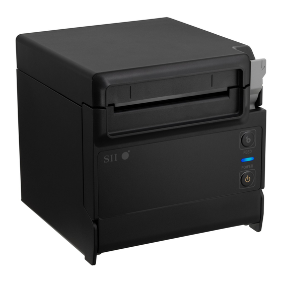
Seiko RP-F10 Series Technical Reference (203 pages)
Brand:
Seiko
| Category:
Printer
| Size: 2.13 MB
Table of Contents
Table of Contents
5
Figure 1-1 Relationship between Input Buffer and Line Buffer
11
Figure 1-2 Line Spacing
12
Figure 1-3 Character Spacing
12
Chapter 1 Terms Used in this Manual
14
Chapter 2 Specifications
14
Printer Specifications
14
Table 2-1 Printer Specifications
14
Sale Destinations
17
Table 2-2 Sale Destinations
17
Figure 2-1 Operating Temperature and Humidity Range
18
Precautions for Use
18
Dimensions
20
Figure 2-2 RP-F10 Dimensions
20
Figure 2-3 RP-F10 Installation Position
21
Label
22
Table 2-3 Thermal Paper Specifications
23
Table 2-4 Specified Thermal Paper Model
23
Thermal Paper Specifications
23
Figure 2-4 Print Area
24
Print Area
24
Cutter Specifications
25
Figure 2-5 Cut Position
25
Table 2-5 Cutter Specifications
25
Power Supply Specifications
26
Figure 2-6 Power Supply Connector (View from Joint Surface)
26
Table 2-6 Power Supply Specifications
26
Table 2-7 Specified AC Adapter Specifications (PW-G2421-W1)
26
Drawer Kick Port Specifications
27
Figure 2-7 Drawer Kick Connector Circuit Sample
27
Table 2-8 Drawer Kick Port Specifications
27
Communication Cable Specifications
28
Specified USB Cable Specifications
28
Table 2-10 Connection Cable for Specified USB Cable
28
Table 2-9 Specified USB Cable Specifications
28
Specified Powered USB Cable Specifications
29
Table 2-11 Specified Powered USB Cable Specifications
29
Table 2-12 Connection Cable for Specified Powered USB Cable
29
Chapter 3 Interface
30
Usb + Usb Host Model
30
Table 3-1 General Specifications of USB Interface
30
USB Interface
30
Figure 3-1 Connector
31
Table 3-2 Pin Assignment of USB Interface
31
Figure 3-2 Screen of [USB] Tab in SII Communication Settings Utility for Windows
32
Figure 3-3 Screen of [Driver Type] Tab in Communication Settings Utility
33
Figure 3-4 Connector
34
Figure 3-5 Connector
34
Table 3-3 General Specifications of USB Host Interface
34
Table 3-4 Pin Assignment of USB Host Interface
34
USB Host Interface
34
Ethernet + Usb Host Model
36
Ethernet Interface
36
Table 3-5 General Specifications of Ethernet Interface
36
Table 3-6 Pin Assignment of Ethernet Interface
36
Table 3-7 Network Communication System
37
Table 3-8 Network Status Indication
37
Table 3-9 Print Communication Protocol (LPR)
37
Table 3-10 Print Communication Protocol (TCP Socket Port)
38
Table 3-11 Protocol for Getting and Setting the Status
38
Table 3-12 Protocol for Monitoring Settings
38
Bluetooth + Usb Host Model
39
Bluetooth Interface
39
Figure 3-6 Bluetooth Interface
39
Table 3-14 General Specifications of Bluetooth Interface
39
Precautions for Use Bluetooth
40
Chapter 4 Function Settings
41
Function Setting Method
41
Changing Memory Switch
42
Figure 4-1 Properties of Printer Driver
42
Figure 4-2 Mode Selection Message
43
Figure 4-3 MS Selection Message
43
Figure 4-4 Function Selection Message (Example: Selected MS1)
44
Figure 4-5 Setting Value Selection Message (Example: Selected Standby LED)
45
Figure 4-6 Setting Value Confirmation Message (Example: Selected Green)
45
Function Settings (Ms)
46
Table 4-1 General Setting 1 (MS1)
46
Table 4-2 Standby LED Selection (MS1-4 to 5)
46
Table 4-3 General Setting 2 (MS2)
47
Table 4-4 Buzzer Count Selection When Error Occurs (MS2-1 to 2)
47
Table 4-5 Buzzer Pattern Selection When Error Occurs (MS2-3 to 4)
47
Table 4-6 General Setting 3 (MS3)
48
Table 4-7 Buzzer Count Selection When Cut Process Completes (MS3-1 to 2)
48
Table 4-8 Buzzer Pattern Selection When Cut Process Completes (MS3-3 to 4)
48
Table 4-9 General Setting 4 (MS4)
49
Table 4-11 Maximum Print Speed Selection (MS4-7 to 8)
50
Table 4-12 General Setting 5 (MS5)
52
Table 4-14 General Setting 6 (MS6)
53
Table 4-16 General Setting 7 (MS7)
54
Table 4-18 General Setting 13 (MS13)
55
Table 4-19 International Character Set
56
Table 4-20 International Character Selection (MS15)
56
Table 4-21 Character Code Table
57
Table 4-22 Character Code Table Setting (MS16)
57
Table 4-23 General Setting 17 (MS17)
58
Table 4-25 General Setting 18 (MS18)
59
Table 4-26 Buzzer Count Selection (MS18-1 to 2)
59
Table 4-27 Buzzer Pattern Selection (MS18-3 to 4)
59
Table 4-28 Bluetooth Setting (MS39)
60
Test Print
61
Figure 4-7 Test Print Sample
61
Chapter 5 Led Indication and Switch Function
62
Printer Status Led Indication
62
Table 5-1 Printer Status
62
Table 5-2 LED Blink Pattern
63
Error and Recovery Procedure
64
Table 5-3 Error and Recovery Procedure
64
Switch
65
FEED Switch
65
POWER Switch
65
Chapter 6 Command Functions
66
Character Codes and Commands
66
JIS Code System
66
Shift-JIS Code System
68
Flash Memory
69
Table 6-1 Memory Area after Initialization
70
Table 6-2 Number of Bytes of Memory Control Information for each Function
71
Table 6-3 Commands Involving Allocation or Release of Memory Area
72
Standard Mode and
75
Page Mode
75
Standard Mode
75
Table 6-4 Printing Procedure for Printing One Page in Page Mode
75
Table 6-5 Printing Procedure for Printing Multiple Pages in Page Mode
76
Figure 6-1 Mapping of Character and Image Data
77
Table 6-6 Maximum Print Area in Page Mode
78
Response Data
79
Table 6-7 Response Identifiers
79
Command Description
81
Printing Command
82
Printingcommand
82
LF Line Feed
82
FF Print and Return to Standard Mode
82
CR Carriage Return
82
ESC FF Print Data in
82
ESC 'J' N Print and Feed Backward
83
ESC 'J' N Print and Feed Forward
83
CAN Cancel Print Data in
84
ESC 'D' N Print and N Lines Feed Forward
84
ESC '2' Set 1/6 Inch Line Spacing
85
ESC '3' N Set Line Spacing
85
Line Spacing
85
Character Set
86
ESC SP N Set Character Right Spacing
86
GS '!' N Specify Character Size
88
ESC '-' N ESC '-' N Specify/Cancel Underline
89
ESC 'E' N Specify/Cancel Bold Print
89
ESC 'G' N Specify/Cancel Double Strike Print
90
ESC 'V' N Specify/Cancel Character 90° Right Rotate
90
ESC '{' N Specify/Cancel Inversion (Flip) Print
91
GS 'B' N Specify/Cancel Reverse Print
91
Character Set
93
ESC '&' y S E [X [D]K]N
95
Register Downloaded Character
95
DC2 'D' N Release/Allocate Downloaded Character Area
96
ESC '%' N Specify/Cancel Downloaded Character Set
96
ESC '?' N Release Downloaded Character
96
DC2 'O' N Specify/Cancel Optional Font
97
DC2 'P' S E y X [D]K Register Optional Font
97
DC2 'Q' Release Optional Font Area
98
Print Position
99
GS 'P' X y Set Basic Calculation Pitch
100
ESC 'D' [N]K NUL Set Horizontal Tab Position
101
HT Horizontal Tab
101
ESC 'A' N Alignment
102
GS 'L' Nl Nh Set Left Margin
102
GS 'W' Nl Nh Set Print Area Width
103
Set Print Area in
104
ESC '$' Nl Nh Specify Absolute Position
106
ESC '\' Nl Nh Specify Relative Position
106
GS '$' Nl Nh Specify Absolute Vertical Position in
107
GS '\' Nl Nh Specify Relative Vertical Position in
108
Image
109
GS '*' X y [D]K Register Downloaded Bit Image
110
GS '/' M N
111
GS '/' M Print Downloaded Bit Image
111
Select Downloaded Bit Image
111
GS 'V' '0' M Xl Xh Yl Yh [D]K
112
Print Raster Bit Image
112
DC2 '=' N Select Image LSB/MSB
114
DC2 'I' N Select Bit Image Scan Method
114
Send Registered NV Graphics Key Code List
116
Delete NV Graphics Data in Batch
116
Delete Specified NV Graphics Data
117
Print Specified NV Graphics Data
117
Select Specified NV Graphics Data
118
Register NV Graphics Data
118
Store Graphics Data in Print Buffer
119
Specify Watermark Print Position
120
Print Position
121
GS ':' Start/End Macro Definition
122
Macro
122
GS '^' R T M Execute Macro
123
Barcode
124
Select HRI Character Font
124
Select HRI Character Print Position
124
Set Barcode Height
125
Set Barcode Width
125
Select Barcode Print Direction
126
Set Barcode N:W Ratio
126
Print Barcode
127
GS 'N' N Set Nominal Narrow Element Width
134
GS 'O' N Set PDF Module Height
134
Two-Dimensional Barcode
134
Print PDF417
134
GS 'P' 1 Model E V Mode Nl Nh [D]K
135
Set QR Code, Data Matrix Module Size
135
Print QR Code
135
Print Data Matrix
136
Print Maxicode
136
GS 'P' 4 0 N [D]N Print GS1 Databar Stacked
137
GS 'P' 4 1 H N [D]N Print GS1 Databar Stacked Omni-Directional
138
GS 'P' 4 2 S N [D]N Print GS1 Databar Expanded Stacked
138
Select QR Code Model
138
Set QR Code Module Size
139
Select QR Code Error Correction Level
139
Store QR Code Data
140
Encode and Print QR Codel Data
140
FS '&' Specify Kanji Mode
141
FS '.' Cancel Kanji Mode
141
Kanji
141
Specify Kanji Print Mode
141
Specify/Cancel Kanji Underline
142
FS 'C' N Select Kanji Code System
143
FS 'S' N1 N2 Set Kanji Spacing
143
DC2 '.' N Select Kanji Font
144
FS 'W' N Specify/Cancel Kanji Quadruple-Size
144
Register User-Defined Character
145
Send 2-Byte Font ID
145
Release/Allocate User-Defined Character Area
146
Auxiliary Functions
147
Select Peripheral Device
147
GS 'C' '0' N M Set Counter Print Mode
148
GS 'C' '1' al Ah Bl Bh N R
148
Set Count Mode
148
GS 'C' '2' Nl Nh Set Counter Value
149
GS 'C' Print Counter
149
Send Printer ID
150
GS 'V' M (2)GS 'V' M N
151
Cut Paper
151
ESC I Full Cut
151
ESC M Partial Cut
151
ESC 'P' M N1 N2
152
Generate Pulse
152
Stamp & Cut
152
DLE DC4 Fn M T Generate Pulse in Real Time
153
GS 'G' '0' M Nl Nh Initialize Maintenance Counter
153
Save Maintenance Counter
154
Send Maintenance Counter
154
DC2 '*' '1' N Defragment User Area
155
DC2 '*' '2' Send Remaining User Area
155
DC2 '*' '6' Send Remaining User Area after Defragment
155
DC2 'K' F [D]K NUL Change Function Settings
156
DC2 'R' N Initialize User Area
156
Change Function Settings
157
DC2 'L' N Send Function Settings
158
DC2 'Q' N Execution Response Request
158
DC2 'T' Test Print
158
ESC 'C' '5' N Enable/Disable Panel Switch
158
Send Status Data
159
Enable/Disable Automatic Status Back
162
Clear Buffer at Error
165
DC3 '(' 'C' 'L' 'R' ')
165
Send Error History
165
DC3 '(' 'R' 'E' 'S' 'E' 'T' DC3 'R' 'E' 'S' 'E' 'T' ')
166
Printer Reset
166
DC2 '>' N Specify Fixed Division
166
DC2 '%' N Specify Number of Dots of Dynamic Division
167
DC2 '~' N Set Print Density
167
DC2 'U' 0
168
Execute Power off
168
Set Iserialnumber
168
Set Print Speed
168
Set Communication Default Value
169
Set Iserialnumber
169
DEL DC4 Fn a N R T1 T2
170
Stop External Buzzer
170
Set External Buzzer
170
Send Status Data in Real Time
171
Dc3
175
DC3 '#' N Select Ruled Line Overlapping Mode
175
DC3 '+' Set Ruled Line on
175
Ruled Line
175
DC3 '-' Set Ruled Line off
176
DC3 'A' Select Ruled Line a
176
DC3 'B' Select Ruled Line B
176
DC3 'C' Clear Ruled Line Buffer
176
DC3 'D' Nl Nh Set Ruled Line (Unit: Dot)
177
DC3 'F' N1 N2 Fill Ruled Line Pattern
177
DC3 'L' Ml Mh Nl Nh Set Ruled Line (Unit: Dot-Line)
177
DC3 'P' Nl Nh Print Ruled Line N Dot-Lines
178
DC3 'P' Print Ruled Line 1 Dot-Line
178
DC3 'V' Nl Nh [D]K Write Ruled Line Image
178
DC2 DC2 Select Download Mode
179
Download Mode
179
Reset Download Mode
179
S' 'W' a [D1]K1 B [D2]K2
179
Rewrite 1-Byte Font
179
Register 1-Byte Font International Character
180
Delete 1-Byte Font
181
Command List
182
Chapter 7 Initialization
186
Initialization
186
Initialization of Settings
187
Initialization by Software Resetting
189
Initialization by Hardware Resetting
189
Appendix A Character Sets (Character Code Table)
190
Character Code Table (Codepage
190
Figure A-1 USA, Standard Europe (Code Page437
190
Figure A-2 Katakana
191
Figure A-3 Multilingual (Code Page850
191
Figure A-4 Portuguese (Code Page860
192
Figure A-5 Canadian-French (Code Page863
192
Figure A-6 Nordic (Code Page865
193
Figure A-7 Turkish (Code Page867
193
Figure A-8 Greek (Code Page737
194
Figure A-9 Latin (Code Page1252
194
Figure A-11 Eastern Europe (Code Page852
195
Figure A-12 Euro (Code Page858
196
Figure A-13 Cyrillic (Code Page855
196
Figure A-14 Arabic (Code Page864
197
Figure A-15 Central European (Code Page1250
197
Figure A-16 Cyrillic (Code Page1251
198
Figure A-17 Greek (Code Page1253
198
Figure A-18 Turkish (Code Page1254
199
International Character Set
200
Figure A-19 International Character Set
200
2-Byte Character
201
Figure A-20 Special Character Set
201
Figure A-21 NEC Special Character Set
201
Figure A-22 NEC Selection of IBM Extended Character Set
202
Figure A-23 IBM Extended Character Set
203
Advertisement
Advertisement
Related Products
Seiko RP-E10 Series
Seiko Rotary Slide Rule
Seiko RC-4000
Seiko RC-4400
Seiko BP-9000
Seiko ColorPainter V-64S
Seiko CT-2000
Seiko DPU-3445
Seiko DPU-414
Seiko DPU-S245-00A-E
Seiko Categories
Watch
Printer
Sewing Machine
Clock
Tuner
More Seiko Manuals
Login
Sign In
OR
Sign in with Facebook
Sign in with Google
Upload manual
Upload from disk
Upload from URL