Sign In
Upload
Manuals
Brands
Red-D-Arc Manuals
Welding System
D502K 5+4
Red-D-Arc D502K 5+4 Manuals
Manuals and User Guides for Red-D-Arc D502K 5+4. We have
1
Red-D-Arc D502K 5+4 manual available for free PDF download: Technical Manual
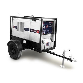
Red-D-Arc D502K 5+4 Technical Manual (82 pages)
CC/CV DC Diesel Welder
Brand:
Red-D-Arc
| Category:
Welding System
| Size: 4.67 MB
Table of Contents
Table of Contents
2
Section 1 - Safety Precautions for Servicing
5
Symbol Usage
5
Servicing Hazards
5
EMF Information
6
Section 2 - Definitions
7
Symbols and Definitions
7
Section 3 - Specifications
8
Weld, Power, and Engine Specifications
8
Dimensions, Weights, and Operating Angles
8
Volt-Ampere Curves
9
Fuel Consumption
10
Duty Cycle and Overheating
10
AC Auxiliary Power Curve
11
Manufacturer's Rating Label
11
Section 4 - Installation
12
Installing Welding Generator (See Section 4-3)
12
Installing Exhaust Pipe
12
Mounting Welding Generator
13
Connecting the Battery
13
Engine Prestart Checks
14
Adding Coolant to Radiator
15
Connecting to Weld Output Terminals
16
Selecting Weld Cable Sizes
17
Connecting to Remote 14 Receptacle RC14
18
Section 5 - Operating Welding Generator
20
Front Panel Controls (See Section 5-2)
20
Description of Front Panel Controls (See Section 5-1)
21
Process/Contactor Control Switch
22
Remote Voltage/Amperage Control
23
Section 6 - Operating Auxiliary Equipment
24
Volt and 240 Volt Receptacles
24
Section 7 - Maintenance
25
Maintenance Label
25
Routine Maintenance
26
Servicing Air Cleaner
28
Inspecting/Cleaning Optional Spark Arrestor
29
Adjusting Engine Speed
30
Servicing Fuel and Lubrication Systems
31
Servicing Engine Cooling System
32
Overload Protection
33
Section 8 - Theory of Operation
34
Section 9 - Explanation of Electrical Parts
36
Section 10 - Troubleshooting
40
Troubleshooting Tables
40
Troubleshooting Circuit Diagram for Welding Generator (Use with Section 10-3)
44
Troubleshooting Values for Circuit Diagram (Use with Section 10-2)
46
Waveforms for Section 10-2
47
Filter Board PC6 Testing Information
48
Filter Board PC6 Test Point Values
49
Field Current Regulator Board PC1 Testing Using LED Board PC9
50
Using Diagnostic Led's on LED Board PC9
51
LED Board PC9 Testing
52
10-10.Diagnostic Led's on LED Board PC9
53
Replacing Brushes and Cleaning Slip Rings
54
10-12.Checking Unit Output after Servicing
55
Section 11 - Disassembly and Reassembly
56
Disassembly of Unit
56
Disassembly of Generator
57
Section 12 - Electrical Diagrams
59
Section 13 - Run-In Procedure
66
Wetstacking
66
Run-In Procedure Using Load Bank
67
Run-In Procedure Using Resistance Grid
68
Section 14 - Parts List
70
Advertisement
Advertisement
Related Products
Red-D-Arc D502K 5+2
Red-D-Arc D503K 5+3 HO
Red-D-Arc D55OK HO
Red-D-Arc DC-400
Red-D-Arc DC-600
Red-D-Arc 10994
Red-D-Arc 11166
Red-D-Arc 11223
Red-D-Arc 11266
Red-D-Arc 11391
Red-D-Arc Categories
Welding System
Portable Generator
More Red-D-Arc Manuals
Login
Sign In
OR
Sign in with Facebook
Sign in with Google
Upload manual
Upload from disk
Upload from URL