Sign In
Upload
Manuals
Brands
Raymarine Manuals
Transceiver
AIS950
Raymarine AIS950 Manuals
Manuals and User Guides for Raymarine AIS950. We have
1
Raymarine AIS950 manual available for free PDF download: Installation Instructions Manual
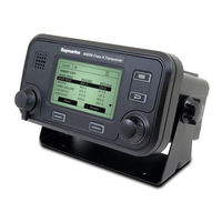
Raymarine AIS950 Installation Instructions Manual (75 pages)
Brand:
Raymarine
| Category:
Transceiver
| Size: 5.02 MB
Table of Contents
Installation Instructions
1
Table of Contents
3
1 Notices
7
Safety Warnings
7
General Notices
7
2 Introduction
9
About AIS
9
Figure 1 the AIS Network
9
Static and Dynamic Vessel Data
10
AIS Operation Licensing
10
3 Operation
11
Display and Controls
11
Figure 2 Transceiver Front Panel
11
Turning the Transceiver on
12
Display Layout
12
Figure 3 Display Layout
12
Main Operating Screens
13
Figure 4 Selection of Main Operating Screen
13
Target List
14
Own Vessel and Voyage Data
14
Figure 5 Target List Screen and Vessel Details View
14
Figure 6 Own Vessel and Voyage Data Screen
14
Own Dynamic Data
15
Figure 7 Own Dynamic Data Screen
15
Received Messages
16
Figure 8 Received Messages Screen
16
Figure 9 Message Details View
16
Alarms Screen
17
Figure 10 Alarms Screen
17
Figure 11 Alarm Details View
17
Target Plot Screen
18
Working with AIS Text and Safety Related Messages (Srms)
18
Figure 12 Target Plot Screen
18
Figure 13 Target Plot Symbols
18
Figure 14 Safety Related Message Notification
19
Figure 15 Message Composition
19
Handling Alarms
20
Figure 16 Alarm Notification Screen
20
Entering Text
21
Long Range Messages
22
Figure 17 Text Entry
22
Figure 18 Long Range Interrogation Notification; Automatic Response Mode Enabled
23
Figure 19 Long Range Interrogation Notification; Manual Response Mode Enabled
23
Figure 20 Long Range Message List and Details Views
23
Passwords and Security
24
The Configuration Menu
24
Figure 21 Password Entry Screen
24
Figure 22 Main Menu Structure
25
Figure 23 Main Menu Screen
26
Figure 24 the Voyage Data Menu
26
Figure 25 the Messages Menu
27
Figure 26 the User Settings Menu
27
Figure 27 the Installation Menu
28
Figure 28 the Maintenance Menu
28
Tanker Mode
29
Figure 29 Diagnostics Menu
29
Figure 30 Tanker Mode Entry Acknowledgement Screen
29
Units Display - Speed and Distance
30
Figure 31 Tanker Mode Exit Screen When Speed Exceeds 3 Knots
30
4 Installation
31
Figure 32 Typical AIS Transceiver Connection
31
What's in the Box
32
Figure 33 What's in the Box
32
Preparing for Installation
33
Installation Procedures
33
Figure 34 AIS Transceiver Dimensions
34
Figure 35 Mounting the AIS Transceiver
34
Figure 36 Panel Mounting the AIS Transceiver
35
Figure 37 Junction Box Dimensions
36
Figure 38 Mounting the Junction Box
36
Figure 39 GPS Antenna Location
37
Figure 40 GPS Antenna Connection
37
Figure 41 VHF Antenna Installation
38
Connecting the Equipment
39
Figure 42 VHF Antenna Connection
39
Figure 43 Connecting the Junction Box to the Transceiver
39
Figure 44 Junction Box Connections
41
Figure 45 Example Connection to External Display Equipment
43
Figure 46 Line Termination Options
43
Figure 47 Power Connection
44
Figure 48 PC Data (RS232) Connection
45
Configuring the AIS950 Transceiver
46
Figure 49 Vessel Dimensions Measurement
47
Changing the Password
49
Confirming Correct Operation
49
Regional Area Settings
49
Figure 50 Regional Areas List Screen
49
Figure 51 Regional Area Editing Screen
50
Figure 52 Regional Area Settings Confirmation Screen
50
5 Technical Specifications
51
Applicable Equipment Standards
51
Physical
51
Environmental
51
Electrical
51
Display and User Interface
52
Internal GPS
52
TDMA Transmitter
52
TDMA Receivers
52
DSC Receiver
53
RF Connections
53
Data Interfaces
53
Power and Data Connector Information
54
6 Technical Reference
55
Interface Sentences
55
Transmission Intervals
56
Sensor Data Input Port
56
Figure 53 Input Port Schematic
56
Bi-Directional Data Ports
57
Output Drive Capability of Bi-Directional Ports
57
DGPS Port
57
RS232 Port
57
Input Data Sentence Formats
57
Figure 54 Data Output Port Schematic
57
Output Data Sentence Formats
66
7 Drawings
70
AIS Transceiver Overall Dimensions
70
Junction Box Overall Dimensions
70
Dash Mount Bracket Fixing Holes (Drill Drawing) (Not to Scale)
71
GPS Antenna Drawing (Not to Scale)
71
8 Installation Record
73
Advertisement
Advertisement
Related Products
Raymarine AIS500
Raymarine AIS700
Raymarine AIS4000
Raymarine AIS250
Raymarine AIS350
Raymarine AIS650
Raymarine AIS Splitter 100
Raymarine axiom 9
Raymarine AXIOM+ Series
Raymarine Axiom Pro Series
Raymarine Categories
Marine Equipment
GPS
Monitor
Autopilot System
Radio
More Raymarine Manuals
Login
Sign In
OR
Sign in with Facebook
Sign in with Google
Upload manual
Upload from disk
Upload from URL