Sign In
Upload
Manuals
Brands
Perkins Manuals
Engine
CR
Perkins CR Manuals
Manuals and User Guides for Perkins CR. We have
1
Perkins CR manual available for free PDF download: Workshop Manual
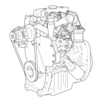
Perkins CR Workshop Manual (240 pages)
3 cylinder, naturally aspirated, and turbocharged diesel engines for agricultural and industrial use
Brand:
Perkins
| Category:
Engine
| Size: 10.55 MB
Table of Contents
Table of Contents
3
General Information
11
Introduction
11
Engine Views
12
Engine Identification
13
Safety Precautions
14
Specifications
14
Engine Lift Equipment
16
Viton Seals
17
POWERPART Recommended Consumable Products
18
Specifications
21
Data and Dimensions
21
Crankshaft Assembly
28
Cylinder Block Assembly
32
Thread Sealant
38
Standard Torque Tensions
39
Special Torque Tensions
40
Aspiration System
40
Lubrication System
41
13 Flywheel and Housing
42
Electrical Equipment
42
Compression Test Data
43
Cylinder Head Assembly
45
General Description
45
Rocker Cover
46
Operation 3-1 to Remove and to Fit
46
Rocker Assembly
47
Operation 3-2 to Remove
47
Operation 3-3 to Fit
48
Operation 3-4 to Dismantle and to Assemble
51
Operation 3-5 to Inspect
52
Valve Tip Clearances
53
Operation 3-6 to Check and to Adjust
53
15 Auxiliary Equipment
54
Special Tools
54
Valve Springs
54
Operation 3-7 to Change the Valve Springs, with the Cylinder Head Fitted
54
Cylinder Head Assembly
56
Operation 3-8 to Remove
56
Operation 3-9 to Fit the Cylinder Head
57
Operation 3-10 to Tighten the Cylinder Head Setscrews and Fasteners
60
Operation 3-11 to Fit Ancillary Components
62
Valves and Valve Springs
64
Operation 3-12 to Remove
64
Operation 3-13 to Fit
65
Operation 3-14 to Inspect and to Correct
66
Valve Guides
67
Operation 3-15 to Inspect
67
Operation 3-16 to Remove
68
Operation 3-17 to Fit
69
Cylinder Head
70
Operation 3-18 to Inspect and to Correct
70
Operation 3-19 to Correct a Valve Seat with a Valve Seat Cutter
71
Operation 3-20 to Fit a Valve Seat Insert
72
Piston and Connecting Rod Assembly
73
General Description
73
Big End Bearing
74
Piston and Connecting Rod Assembly
76
Piston Rings
83
Connecting Rod
86
Small End Bush
86
Crankshaft Assembly
87
General Description
87
Crankshaft Pulley
88
Rear Oil Seal Assembly
89
Thrust Washers
91
Main Bearings
95
Crankshaft
97
Timing Case and Drive Assembly
101
General Description
101
Timing Case Cover
102
Operation 6-1 to Remove
102
Operation 6-2 to Fit
103
Front Oil Seal
104
Operation 6-3 to Remove and to Fit
104
Idler Gear and Hub
105
Operation 6-4 to Remove
105
Operation 6-5 to Fit
106
Fuel Pump Gear
108
Operation 6-6 to Remove a Gear from a Tapered Shaft
108
Operation 6-7 to Fit a Gear to a Tapered Shaft
109
Operation 6-8 to Remove a Gear Fitted to a Hub
110
Operation 6-9 to Fit a Gear to a Hub
111
Camshaft Gear
113
Operation 6-10 to Remove
113
Operation 6-11 to Fit
114
Crankshaft Gear
115
Operation 6-12 to Remove and to Fit
115
Timing Case
115
Timing Case
116
Operation 6-13 to Remove
116
Operation 6-14 to Fit
117
Camshaft
119
Operation 6-15 to Remove and to Fit
119
Cylinder Block Assembly
121
General Description
121
Cylinder Block
122
Operation 7-2 to Assemble
123
Operation 7-3 to Inspect
124
Cylinder Liner
125
Operation 7-5 to Inspect
129
Engine Timing
131
General Description
131
Engine Timing
132
Operation 8-1 to Set the Engine to Top Dead Centre (TDC)
132
Operation 8-2 to Check the Valve Timing
133
Operation 8-3 to Check the Locking Angle of the Fuel Injection Pump Timing
134
Operation 8-4 to Check the Timing of Pin-Timed Fuel Injection Pumps
136
Aspiration System
137
General Description
137
Turbocharger
138
Operation 9-1 to Remove
138
Operation 9-2 to Fit
140
Turbocharger Faults
142
Closed Breather System
144
Operation 9-3 to Renew the Engine Breather Valve
144
Open Breather System
145
Operation 9-4 General Information
145
Operation 9-5 to Clean
146
Operation 9-6 to Renew
147
Breather Separator
148
Operation 9-7 to Renew the Engine Oil Separator
148
Lubrication System
149
General Description
149
Lubrication System Flow Diagram
150
Filter Canister Operation 10-1 to Renew
151
Filter Head
152
Operation 10-2 to Remove and to Fit
152
Canister Type Lubricating Oil Cooler
153
Sump
154
Operation 10-4 to Remove
154
Operation 10-5 to Fit
155
Operation 10-6 to Remove a Sump Retained by Clamps
158
Operation 10-7 to Fit a Sump Retained by Clamps
160
Oil Strainer and Suction Pipe Assembly
164
Operation 10-9 to Inspect and to Correct
165
Lubricating Oil Pump
166
Operation 10-11 to Fit
167
Operation 10-12 to Inspect
169
Relief Valve
170
Operation 10-13 to Dismantle and to Assemble
170
Operation 10-14 to Inspect
171
Fuel System
173
General Description
173
Fuel Filter
176
Operation 11-1 Fuel Filter Types
176
Operation 11-2 to Renew the Element Type Filter
177
Operation 11-3 to Renew the Quick Release Type Filter
178
Atomisers
179
Operation 11-4 Atomiser Faults
179
Operation 11-5 to Remove Atomisers Retained by a Clamp
180
Operation 11-6 to Fit Atomisers Retained by a Clamp
181
Operation 11-7 to Remove Atomisers Retained by a Gland Nut
182
Operation 11-8 to Fit Atomisers Retained by a Gland Nut
183
Fuel Lift Pump
184
Operation 11-9 to Remove and to Fit
184
Operation 11-10 to Dismantle
185
Operation 11-11 to Assemble
186
Operation 11-12 to Test
187
Delphi Fuel Injection Pumps
188
General Description
188
General Description
199
11 Fuel System
205
12 Cooling System
205
General Description
217
General Description
221
Alternator Fault Diagnosis
227
Not Used
235
List of Special Tools
237
Advertisement
Advertisement
Related Products
Perkins CP
Perkins 100 Series
Perkins 1000 Series
Perkins 102-05
Perkins 103-06
Perkins 103-07
Perkins 103-09
Perkins 103-10
Perkins 103-13
Perkins 103-15
Perkins Categories
Engine
Lifting Systems
Inverter
Speakers
Analytical Instruments
More Perkins Manuals
Login
Sign In
OR
Sign in with Facebook
Sign in with Google
Upload manual
Upload from disk
Upload from URL