Panasonic SA-VK81DGCS Manuals
Manuals and User Guides for Panasonic SA-VK81DGCS. We have 2 Panasonic SA-VK81DGCS manuals available for free PDF download: Service Manual
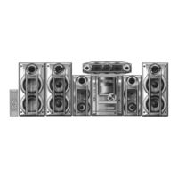
Panasonic SA-VK81DGCS Service Manual (154 pages)
DVD Stereo System
Brand: Panasonic
|
Category: Stereo System
|
Size: 24.83 MB
Table of Contents
Advertisement
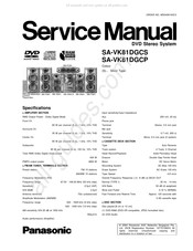
Panasonic SA-VK81DGCS Service Manual (154 pages)
DVD Stereo System
Brand: Panasonic
|
Category: Stereo System
|
Size: 25.46 MB