Sign In
Upload
Manuals
Brands
Oracle Manuals
Storage
Pillar Axiom
Oracle Pillar Axiom Manuals
Manuals and User Guides for Oracle Pillar Axiom. We have
1
Oracle Pillar Axiom manual available for free PDF download: Service Manual
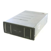
Oracle Pillar Axiom Service Manual (317 pages)
Oracle Pillar Axiom SAN Storage system Service guide
Brand:
Oracle
| Category:
Storage
| Size: 2.79 MB
Table of Contents
Copyright Notice
2
Table of Contents
3
Chapter 1, Introduction to Pillar Axiom Service Procedures
20
Audience
20
Warnings and Cautions
21
Safety Notice Conventions
21
Hazard Signal Words
21
About Axiom Product Configurations
22
Table 1 Pillar Axiom 500 Series Components
22
Required Tools
23
Table 2 Required Tools
23
Electrostatic Discharge (ESD) Precautions
24
Contact Information
25
Table 3 Contacts at Pillar Data Systems
25
Chapter 2, Service the Pillar Axiom Storage System
26
Introduction to System Service Procedures
26
Initiate Guided Maintenance
27
Log in to the Graphical User Interface (GUI)
28
Enter Guided Maintenance for the Target FRU
29
Figure 1 Hardware Health
30
Identify the Target FRU (Optional)
31
Prepare the System for FRU Replacement
32
Replace the Target FRU
33
Table 4 Pillar Axiom FRU Replacement Procedures
34
Fail Back the Control Unit (Optional)
35
Verify the Status of the Replacement FRU
35
System-Wide Service Procedures
36
Back up Data
36
Remove Rack Doors
38
Figure 2 Sample 42U Rack Front Door
38
Figure 3 Different Types of Rack Door Hinges
39
Remove Rack Side Panels
40
Figure 4 Sample 42 U Side Panels
40
Attach the Rack Doors
41
Attach the Rack Side Panels
41
Chapter 3, Service the Pilot and Pilot Frus
43
Introduction to Pilot Service Procedures
43
Map of Pilot Frus
45
Figure 5 Schematic of Replaceable Pilot Frus
45
Table 5 Pilot FRU Replacement Tasks
45
Pilot FRU Part Numbers
46
Replace Pilot Bezels
46
Figure 6 Pilot Bezel Leds
46
Table 6 Pilot Frus
46
Figure 7 Pilot Bezel Ejector Tabs
47
Remove a Pilot Bezel
47
Table 7 Pilot Bezel Replacement Tasks
47
Attach a Pilot Bezel
48
Replace Pilot Control Units
49
Figure 8 Pilot CU
49
Table 8 Pilot CU Replacement Tasks
49
Figure 9 Disk Drive LED on Pilot CU
50
Identify a Pilot Control Unit
50
Remove a Pilot Control Unit
51
Figure 10 Bezel Adapter Flange
52
Insert a Pilot Control Unit
53
Figure 11 Pilot CU Support Brackets
54
Reset the Primary Password, Public IP, or Pilot Identity
55
Figure 12 USB Key in a Pilot Control Unit
56
Chapter 4, Service the Slammer and Slammer Frus
58
Introduction to Slammer Service Procedures
58
Table 9 Slammer FRU Replacement Tasks
60
Figure 13 Schematic of Replaceable Slammer Frus
63
Map of Slammer Frus
63
Slammer FRU Part Numbers
64
Table 10 Slammer FRU Part Numbers
64
Replace Slammer Batteries
65
Figure 14 Slammer Battery FRU
65
Figure 15 Slammer Battery Location
66
Table 11 Slammer Battery LED Status
66
Remove a Slammer Battery
67
Table 12 Battery Replacement Tasks
67
Figure 16 Slammer Battery Screws
68
Insert a Slammer Battery
69
Table 13 Battery Shelf Life
69
Table 14 Battery Operational Life
70
Replace Slammer Bezels
72
Figure 17, Slammer Bezel
72
Table 15 Slammer Bezel Replacement Tasks
72
Figure 18 Slammer Bezel Ejector Tabs
73
Remove a Slammer Bezel
73
Attach a Slammer Bezel
74
Figure 19 Receptacle for the Slammer Bezel Power Connector
74
Replace Slammer Fan Modules
75
Figure 20 Slammer Fan FRU
75
Figure 21 Slammer Fan Location
76
Table 16 Slammer Fan LED Status
76
Remove a Slammer Fan Module
77
Table 17 Fan Replacement Tasks
77
Figure 22 Slammer Fan FRU Screws
78
Insert a Slammer Fan Module
79
Replace Slammer Motherboard Trays
80
Figure 23 Slammer Motherboard Tray
81
Figure 24 Motherboard Tray Assembly Location
82
Figure 25, Motherboard Tray Ejector
82
Table 18 Slammer Motherboard LED Status
83
Table 19 Motherboard Tray Replacement Tasks
83
Remove a Slammer Motherboard Tray
85
Insert a Slammer Motherboard Tray
86
Replace Slammer Network Interface Modules
89
Figure 26 Network Interface Module (Optical) FRU
90
Figure 27 Network Interface Module (Optical) Location
91
Table 20 Slammer Network Interface Module LED Status
91
Table 21 Network Interface Module Replacement Tasks
92
Remove a Slammer Network Interface Module
93
Figure 28 Network Interface Module Ejector
94
Insert a Slammer Network Interface Module
95
Replace Slammer Power Supplies
98
Figure 29 Slammer Power Supply FRU
98
Figure 30 Slammer Power Supply Location
99
Table 22 Slammer Power Supply LED Status
99
Remove a Slammer Power Supply
100
Table 23 Power Supply Replacement Tasks
100
Insert a Slammer Power Supply
101
Figure 31 Power Supply Correctly Positioned
102
Replace Slammer Private Interconnect Modules
103
Figure 32 Slammer Private Interconnect Module FRU
104
Figure 33 Private Interconnect Module Location
105
Table 24 Slammer Private Interconnect Module LED Status
105
Table 25 Private Interconnect Module Replacement Tasks
106
Remove a Slammer Private Interconnect Module
107
Figure 34 Private Interconnect Module Ejector
108
Insert a Slammer Private Interconnect Module
109
Replace Slammer PCI Cards
111
Figure 35 Sample PCI Card
112
Figure 36 Riser PCI Slots in a Network Interface Module
112
Table 26 PCI Card Replacement Tasks
113
Remove a Slammer PCI Card
114
Insert a Slammer PCI Card
115
Figure 37 PCI Card and Open PCI Slots
116
Figure 38 PCI Card Faceplate Secured to the Slammer Chassis
117
Replace Slammer Chassis
119
Figure 39 Slammer Chassis Midplane
120
Figure 40 Slammer Bezel Leds
121
Table 27 Leds on the Slammer Bezel
121
Table 28 Slammer Chassis Replacement Tasks
122
Remove a Slammer Chassis
124
Insert a Slammer Chassis
126
Chapter 5, Service the Brick and Brick Frus
130
Introduction to Brick Service Procedures
130
Table 29 Brick FRU Replacement Tasks
131
Figure 41 Schematic of Replaceable Brick Frus
133
Map of Brick Frus
133
Brick FRU Part Numbers
134
Table 30 Brick Frus
134
Replace Brick Bezels
135
Figure 42 Brick Bezel
135
Table 31 Brick Bezel Replacement Tasks
135
Attach a Brick Bezel
136
Figure 43 Brick Bezel Ejector Tabs
136
Remove a Brick Bezel
136
Replace Brick Disk Drives
137
Figure 44 Disk Drive FRU
137
Figure 45 Location of a Disk Drive
138
Table 32 Leds on a Disk Drive Carrier
138
Table 33 Disk Drive Replacement Tasks
140
Remove a Brick Disk Drive
141
Insert a Brick Disk Drive
142
Replace Brick es Modules
144
Figure 46 es Module FRU
144
Figure 47 es Module Location
145
Table 34 Brick es Module LED Status
145
Remove a Brick es Module
146
Table 35 es Module Replacement Tasks
146
Insert a Brick es Module
147
Replace Brick Power Supply / Fan Modules
149
Figure 48 Power Supply / Fan Module FRU
149
Figure 49 Brick Power Supply / Fan Module Location
150
Table 36 Brick Power Supply / Fan Module LED Status
150
Table 37 Power Supply / Fan Module Replacement Tasks
151
Remove a Brick Power Supply / Fan Module
152
Insert a Brick Power Supply / Fan Module
153
Replace Brick RAID Controllers
155
Figure 50 RAID Controller FRU
155
Figure 51, Brick RAID Controller Location
155
Table 38 Brick RAID Controller LED Status
156
Table 39 RAID Controller Replacement Tasks
157
Remove a Brick RAID Controller
158
Insert a Brick RAID Controller
159
Replace Brick Spare Disk Drives
161
Figure 52 Spare Disk Drive FRU
162
Figure 53 Spare Disk Drive Location
162
Table 40 Brick Spare Disk Drive LED Status
163
Remove a Brick Spare Disk Drive
164
Table 41 Spare Disk Drive Replacement Tasks
164
Insert a Brick Spare Disk Drive
166
Replace Brick Chassis
168
Figure 54 Brick Chassis
169
Figure 55 Brick Chassis Midplane
169
Figure 56 Brick Bezel Leds
170
Table 42 Brick Bezel LED Status
170
Table 43 Brick Chassis Replacement Tasks
171
Remove a Brick Chassis
173
Insert a Brick Chassis
175
Appendix A, Safety Statements
178
Introduction to Safety Statements
178
Safety Statements
178
Warning Notices
179
Table 44 Electrical Warning in Other Languages
179
Lightning Activity Warning
183
Table 45 Lightning Warning in Other Languages
183
Power Supply Warning
185
Table 46 Power Supply Warning in Other Languages
185
Installation Warning
188
Main Power Disconnect Warning
188
Table 47 Power Disconnect Warning in Other Languages
188
Table 48 Install Instructions Warning in Other Languages
188
Power Disconnect Warning
189
Table 49 Warnings for Norway and Sweden
189
Warning Statement for Norway and Sweden
189
Restricted Access Area Warning
190
Table 50 Restricted Access Warning for Other Languages
190
Product Disposal Warning
192
Table 51 Product Disposal Warning for Other Languages
192
Jewelry Removal Warning
193
Table 52 Jewelry Removal Warning for Other Languages
194
Qualified Personnel Warning
196
Table 53 Qualified Personnel Warning for Other Languages
196
Table 54 Warnings for Finland
197
Table 55 Warnings for Sweden
197
Warning Statement for Finland
197
Warning Statement for Sweden
197
Power Cabling Warning
198
Table 56 Power Cabling Warning for Other Languages
198
Supply Circuit Warning
199
Table 57 Supply Circuit Warning for Other Languages
199
Table 58 Voltage Mismatch Warning for Other Languages
200
Voltage Mismatch Warning
200
SELV Circuit Warning
202
Table 59 SELV Circuit Warning for Other Languages
202
Incorrect Connection Warning
205
Table 60 Bad Connection Warning for Other Languages
205
Caution Notices
206
Appendix B, Slammer and Brick LED Statuses
209
Introduction to LED Statuses
209
Slammer LED Statuses
210
Table 61 Leds on the Slammer Bezel
211
Figure 57 Leds on the Front of the Slammer Chassis
212
Table 62 Slammer Battery LED Status
212
Table 63 Slammer Fan LED Status
212
Table 64 Slammer Motherboard LED Status
213
Figure 58 Leds on the Back of the Slammer Chassis
214
Table 65 Slammer CU LED Status
214
Table 66 Slammer FC Circuit LED Status
215
Table 67 Slammer FS Port LED Status
215
Table 68 Slammer Copper Gbe Network Port Status
216
Table 69 Slammer Optical Gbe Network Port Status
216
Table 70 Slammer Network Interface Module LED Status
216
Table 71 Slammer Power Supply LED Status
216
Brick LED Statuses
217
Figure 59 Brick Bezel Leds
217
Table 72 Slammer Private Interconnect Module LED Status
217
Figure 60 Disk Drive Carrier Numbering in a Brick
218
Table 73 Brick Bezel LED Status
218
Figure 61 Disk Drive Carrier Leds
219
Table 74 Leds on a Disk Drive Carrier
219
Figure 62 Leds on the Back of the Brick Chassis
221
Table 75 Brick Power Supply / Fan Module LED Status
222
Table 76 Brick RAID Controller LED Status
223
Table 77 Brick es Module LED Status
224
Table 78 Brick Spare Disk Drive LED Status
224
Appendix C, Private Management Network and SSF Cable Reference
226
Introduction to Private Management Network and SSF Cable Tables
226
Hardware Component Designators
227
Table 79 Cable Connection Designations
227
Hardware Maps by Component Designator
229
Figure 63, FRU Location by Designator (1-Slammer System)
229
Figure 64 FRU Location by Designator (2-Slammer System)
231
FRU Cable Connections Reference
232
Table 80 FRU Cable Table Reference
233
Cable Reference Tables for Pilots
235
Pilot Cabling in a 1-Slammer System
235
Table 81 Pilot CU0 in a 1-Slammer System
236
Table 82 Pilot CU1 in a 1-Slammer System
236
Pilot Cabling in a 2-Slammer System
237
Table 83 Pilot CU0 in a 2-Slammer System
237
Table 84 Pilot CU1 in a 2-Slammer System
237
Cable Reference Tables for Private Interconnect Modules
238
Private Interconnect Module Cabling in a 1-Slammer System
238
Table 85, Slammer 1 / CU0 Private Interconnect Module (1 Slammer)
238
Table 86, Slammer 1 / CU1 Private Interconnect Module (1 Slammer)
238
Private Interconnect Module Cabling in a 2-Slammer System
241
Cable Reference Tables for Bricks
246
RAID Controller Cabling in a 1-Slammer System
246
Table 91, Cabling Bricks 1, 2, 3, and 4
248
Table 92 Cabling Bricks 5, 6, 7, and 8 (1 Slammer)
249
Table 93 Cabling Bricks 9, 10, 11, and 12 (1 Slammer)
251
RAID Controller Cabling in a 2-Slammer System
254
Table 94, Cabling Bricks 13, 14, 15, and 16
254
Table 95 Cabling Bricks 5, 6, 7, and 8 (2 Slammers)
255
Table 96 Cabling Bricks 9, 10, 11, and 12 (2 Slammers)
256
Appendix D, Slammer LED Startup Progress Codes
259
Introduction to LED Startup Codes
259
LED Startup Progress Codes
260
Table 97 Code Translation for the FLT LED
260
Table 98 Code Translation for the ACT LED
261
Table 99 Code Translation for the ST LED
261
Table 100 Slammer LED Startup Codes
263
Appendix E, Axiom Component Power Consumption
265
Introduction to Component Power Consumption
265
Single-Phase Pdus
266
Figure 65 Single-Phase PDU Circuit Breakers (Front View)
266
Figure 66 Single-Phase PDU Outlet Distribution (Back View)
266
Three-Phase Pdus
267
Figure 67 Three-Phase PDU Outlet Distribution
267
Figure 68 Three-Phase PDU Circuit Breakers
267
PDU Connections
268
Cabling 115 V Single-Phase Pdus
268
Figure 69 PDU Connections for 115 V / 20 a Power (2 Pdus)
269
Figure 70 PDU Connections for 115 V / 20 a Power (4 Pdus)
270
Cabling 230 V Single-Phase Pdus
271
Figure 71 PDU Connections for 230 V / 30 a Power (2 Pdus)
272
Cabling 208 V Three-Phase Pdus
273
Figure 72 PDU Connections for 208 V / 30 a Power (2 Pdus)
274
Current and Power Summary
275
Table 101 Current and Power in a 115 V System
275
Table 102 Current and Power in a 230 V System
276
Component Configuration Limits
277
Table 103 System Configurations for 20 a Service
277
Table 104 System Configurations for 30 a Service
279
Appendix F, Return a Failed Component
280
Appendix G, Hardware Specifications
282
Introduction to Hardware Specifications
282
Axiom Hardware Specifications
283
System Power Requirements
284
System Environmentals
284
Table 105 System Altitude Specifications
284
Table 106 System Temperature and Humidity Specifications
285
System Regulatory Agency Compliance
286
Table 107 System Acoustics Specification
286
Table 108 System Random Vibration Specifications
286
Regulatory Agency Compliances
287
Table 109 Safety and Quality Standards
287
FCC Warning Statement
288
Table 110 EM Emissions & Immunity
288
European Union Compliance Statement
289
System Packaging and Transportation
291
System Warranty
291
Pilot Hardware Specifications
291
Pilot Dimensions and Weight
292
Pilot Power Characteristics
292
Table 111 Pilot Dimensions and Weight (both Control Units)
292
Table 112 Pilot Power Characteristics (Per Control Unit)
292
Pilot Regulatory Agency Compliance
293
Pilot Packaging and Transportation
294
Table 113 Pilot Safety & Quality Standards
294
Slammer Hardware Specification
295
Slammer Dimensions and Weight
295
Slammer Power Characteristics
295
Table 114 Slammer Dimensions and Weight
295
Table 115 Slammer Power Characteristics
295
Slammer Regulatory Agency Compliance
296
Table 116 Slammer Safety & Quality Standards
296
Table 117 Slammer EM Emissions & Immunity
297
Slammer Packaging and Transportation
298
Brick Hardware Specification
298
Brick Dimensions and Weight
298
Table 118 Brick Dimensions and Weight
298
Brick Power Characteristics
299
Table 119 Brick Power Characteristics
299
Brick Regulatory Agency Compliance
300
Table 120 Brick Safety & Quality Standards
300
Brick Packaging and Transportation
301
Table 121 Brick EM Emissions & Immunity
301
Axiom PDU Hardware Specification
302
Pillar Rack Hardware Specification
303
Figure 73 Maximum Tilt Angles for Stationary Pillar 42 U Racks
306
Index
307
Advertisement
Advertisement
Related Products
Oracle PU2SL
Oracle Retail Place 12.2
Oracle PREMIERE
Oracle Dual Port 25 Gb
Oracle Temple PH 1000
Oracle 21C
Oracle 3.2 TB NVMe
Oracle 7116970
Oracle 9200A
Oracle Database Appliance
Oracle Categories
Server
Storage
Network Hardware
Software
Controller
More Oracle Manuals
Login
Sign In
OR
Sign in with Facebook
Sign in with Google
Upload manual
Upload from disk
Upload from URL