Sign In
Upload
Manuals
Brands
Olympus Manuals
Security Sensors
EPOCH 1000 Series
Olympus EPOCH 1000 Series Manuals
Manuals and User Guides for Olympus EPOCH 1000 Series. We have
1
Olympus EPOCH 1000 Series manual available for free PDF download: User Manual
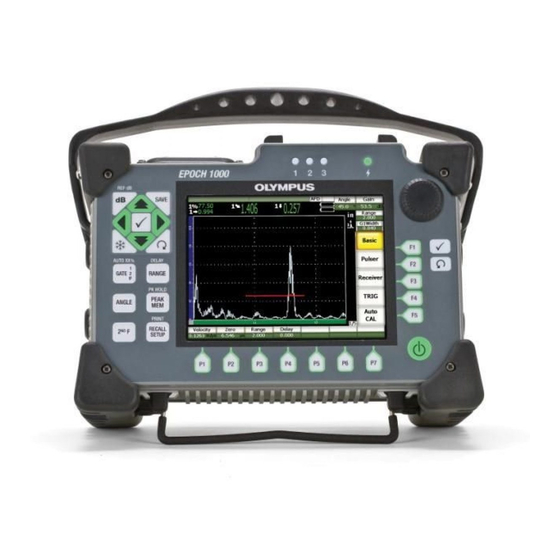
Olympus EPOCH 1000 Series User Manual (364 pages)
Brand:
Olympus
| Category:
Security Sensors
| Size: 8.28 MB
Table of Contents
Table of Contents
3
List of Abbreviations
11
Labels and Symbols
13
Table 1 Content of the Rating Plate Label
14
Important Information - Please Read before Use
17
Intended Use
17
Instruction Manual
17
Instrument Compatibility
18
Repair and Modification
18
Safety Symbols
18
Safety Signal Words
19
Notes Signal Words
20
Safety
20
Warnings
20
WEEE Directive
21
EMC Directive Compliance
22
China Rohs
22
Warranty Information
23
Technical Support
23
Preface
25
Product Description
25
EPOCH 1000 Series Models
26
About this Document
27
Audience
27
Typographical Conventions
28
If You Have Documentation Comments
28
Table 2 Typographic Conventions
28
Revision History
29
Table 3 Revision History
29
EPOCH 1000 Series Hardware Features
31
Figure 1-1 Overview of the EPOCH 1000I Hardware
32
Hardware Overview
32
Front Panel User Interface
33
Figure 1-2 the EPOCH 1000I Hardware User Interface Elements
33
General Purpose Keys and Knob
34
Figure 1-3 General Purpose Keys and Knob
34
Function and Parameter Keys
35
Parameter Adjustment
35
Figure 1-4 [F<N>] and [P<N>] Keys Pointing to Software Buttons
35
About the Direct-Access Keypad
36
Figure 1-5 the English Direct-Access Keypad with Model Differences
37
Table 4 English Keypad Key Description
37
About Indicators
38
USB Keyboard and Mouse Control
39
Connectors
39
Figure 1-6 Front Panel Indicator Lights
39
Conventional Transducer Connections
40
Figure 1-7 Location of the Conventional Transducer Connectors
40
Phased Array Transducer Connector (EPOCH 1000Ir/1000I Only)
41
Figure 1-8 the Connector for the Phased Array (PA) Probe
41
Input/Output Connectors
43
Figure 1-9 Phased Array Connection Cover
43
Battery Compartment Connections
44
Figure 1-10 the ALARMS and ANALOG out Connectors
44
Computer Connection Compartment
45
Figure 1-11 Battery Compartment Cover
45
Figure 1-12 the Connectors Behind the Computer Connection Compartment Door
46
Table 5 Computer Connection Compartment Connectors
46
Various Hardware Features
47
Removable Rubber Handle
47
Instrument Stands
47
Figure 1-13 Tilting Angles Using the Bottom and Rear Stands
48
O-Ring Gasket and Membrane Seals
48
Display Protection
48
Environmental Ratings
49
Powering the EPOCH 1000 Series
51
Starting the EPOCH 1000 Series
52
Figure 2-1 Location of the EPOCH 1000 Power Key and Indicator
52
Table 6 Power Indicator Status
52
Using the AC Line Power
53
Figure 2-2 the Beam Setup Page Appearing at Startup When a PA Probe Is Connected
53
Using Battery Power
54
Figure 2-3 the AC Adaptor Plug
54
Figure 2-4 the Battery Charge Indicator
55
Charging the Battery
56
Replacing the Battery
58
Figure 2-5 Opening the Battery Compartment
58
EPOCH 1000 Series Software Features
61
Figure 3-1 Exploded View of the Software Main Display Elements
62
About the Menu System
62
Software Main Display
62
Figure 3-2 Overview of the Menu System in UT Operation Mode
63
Figure 3-3 the Menu Indicator (1/5)
63
About the Convention to Identify Menu Elements
64
Figure 3-4 Concise Convention to Identify Menu Elements
65
About the Focus
66
About Button Types
66
Figure 3-5 the Focus Is on the Element Appearing Yellow
66
Table 7 Button Types
66
About the File Name/Message Bar
67
About Software Indicators
67
Figure 3-6 Message Bar with a File Name Example
67
Figure 3-7 Message Bar with a Message Example
67
Table 8 Software Indicators
68
About Permanent Parameters
68
Figure 3-8 Example of Software Indicators
68
About Direct-Access Parameters
69
About Measurement Reading Boxes
69
Figure 3-9 Example of the Angle and Gain Permanent Parameters
69
Figure 3-10 Example of the Range and Delay Direct-Access Parameters
69
Figure 3-11 Example of Measurement Reading Boxes with Their Icons
69
About the Live-Scan Area
70
Figure 3-12 Example the Live-Scan Area in A/S Vert Mode
70
About Flags
71
Figure 3-13 the Area Displaying Flags
71
Table 9 Flag Description
71
Menu Contents
73
Table 11 Content of the 1/5 Standard Menu in UT Mode
74
Table 10 Standard Menus in UT Mode
74
Conventional UT Mode Menus
74
Table 12 Content of the 2/5 Standard Menu in UT Mode
75
Table 13 Content of the 3/5 Standard Menu in UT Mode
75
Table 14 Content of the 4/5 Standard Menu in UT Mode
75
Table 15 Content of the 5/5 Standard Menu in UT Mode
75
Phased Array Mode Menus
76
Table 16 Phased Array Standard Menus
76
Table 17 Content of the 1/5 Standard Menu in PA Mode
77
Table 18 Content of the 2/5 Standard Menu in PA Mode
77
Table 19 Content of the 3/5 Standard Menu in PA Mode
77
About Setup
78
Table 20 Content of the 4/5 Standard Menu in PA Mode
78
Table 21 Content of the 5/5 Standard Menu in PA Mode
78
Figure 3-14 the Beam Setup Page and Its Elements
79
Color Setup Page
80
Figure 3-15 the Color Setup Page
80
A-Scan Setup Page
81
Figure 3-16 A-Scan Setup Page
81
Meas Setup Page
83
Figure 3-17 the Meas Setup Page
83
Figure 3-18 Example of Measurement Reading Boxes with Icons
84
Table 22 Available Measurement Readings
84
General Setup Page
88
Figure 3-19 the General Setup Page
88
Owner Info (Inst Setup Group)
90
Figure 3-20 the Owner Info Setup Page
90
Status Setup Page
91
Display Setup Page (Phased Array Mode Only)
91
Figure 3-21 the Status Setup Page
91
Figure 3-22 the Image Overlay Setup Page
92
Basic Procedures
93
Navigating in the Menu Structure
93
Navigating in a Setup Page
94
Changing a Parameter Value
95
Entering an Alphanumeric Value Using the Virtual Keyboard
96
Figure 3-23 the Owner Info Setup Page with Its Virtual Keyboard
97
Interacting with a Dialog Box
98
Managing Data with Gageview Pro Interface Program
98
Figure 3-24 Dialog Box Example
98
Adjusting the Pulser/Receiver (Conventional UT Mode)
101
Adjusting the System Sensitivity (Gain)
101
Using the AUTO-XX% Feature
102
Setting Reference Gain and Scanning Gain
103
Pulser Adjustments
104
Pulse Repetition Frequency (PRF)
104
Pulse Energy (Voltage)
105
Damping
106
Test Mode
106
Pulser Waveform
107
Pulser Frequency Selection (Pulse Width)
108
Receiver Adjustments
108
Filter Group
108
Digital Receiver Filters
109
Standard Filter Set
109
Advanced Filter Set
110
Waveform Rectification
111
Custom Filter Sets
112
Managing Special Waveform Functions (Conventional UT Mode)
113
Reject
113
Peak Memory
114
Figure 5-1 Horizontal Line Indicating the Reject Level
114
Figure 5-2 Peak Memory Signal Envelope Example
115
Peak Hold
116
Freeze
116
Grid Modes
117
Figure 5-3 Selecting the X-Axis Grid Mode
118
Figure 5-4 the X-Axis Grid Modes
119
Figure 5-5 the Y-Axis Grid Modes
120
Gates (Conventional UT Mode)
121
Measurement Gates 1 and 2
122
Figure 6-1 Gate 1 and Gate 2
122
Figure 6-2 the Gate 1 Submenu
123
Quickly Adjusting Basic Gate Parameters
124
Figure 6-3 the Direct-Access Gate Button
124
Interface Gate (Optional)
125
Gate Measurement Modes
125
Figure 6-4 the Gates Setup Page
126
Figure 6-5 Arrow Indicating Measurement Trigger in Edge, Peak, and 1Stpeak Modes
127
Viewing Measurement Readings
128
Gate Tracking and Echo-To-Echo Measurements
128
Figure 6-6 Echo-To-Echo Measurement Example
129
Operating in Time-Of-Flight Mode
130
Using the Zoom
131
Activating the Zoom
131
Zoom Applications
131
Gate Alarms
132
Threshold Alarms
132
Minimum Depth Alarm
133
Minimum Depth Alarm with a Single Gate
133
Figure 6-7 Gate Tick Marks Indicating Alarm Threshold Type
133
Minimum Depth Alarm with Gate Tracking
134
Figure 6-8 Minimum Depth Alarm Marker
134
Reference Cursors
135
Cursors a and B
135
Activating and Positioning Cursors
136
Figure 7-1 A-Scan with Active Reference Cursors
136
Cursor Measurements
137
Input and Output Features
139
VGA Output
139
Analog Outputs
140
Figure 8-1 the VGA/RS-232 Output Connector
140
Figure 8-2 the A-Out Setup Page
141
Trigger Input and Output
142
Serial Communication (RS-232)
143
USB Communication
143
USB Client
143
USB Host
143
Serial/Usb Command Protocol
144
Calibrating the EPOCH 1000 Series (Conventional UT Mode)
145
Getting Started
146
Calibration Modes
147
Straight Beam Modes
148
Angle Beam Modes
148
Calibrating with a Straight Beam Transducer
149
Figure 9-1 Example of a Gated Calibration Signal
150
Figure 9-2 the Enter Value for Zero Cal Dialog Box
150
Figure 9-3 the Second Gated Calibration Signal
151
Calibrating with a Delay Line Transducer
152
Figure 9-4 Example of a Gated Calibration Signal
154
Figure 9-5 the Enter Value for Zero Cal Dialog Box
155
Figure 9-6 the Second Gated Calibration Signal
156
Calibrating with a Dual Element Transducer
157
Figure 9-7 Example of a Gated Calibration Signal
159
Figure 9-8 the Enter Value for Zero Cal Dialog Box
160
Calibrating in Echo-To-Echo Mode
161
Figure 9-9 the Second Gated Calibration Signal
161
Figure 9-10 Example of a Gated Calibration Signal
164
Figure 9-11 the Enter Value for Velocity Cal Dialog Box
164
Calibrating to Known Sound Path Values with an Angle Beam Transducer
165
Locating the Beam Index Point
166
Figure 9-12 IIW Block with Probe at 0 Mark
166
Verifying the Refracted Angle
167
Figure 9-13 Using the Peak Memory to Find the BIP
167
Figure 9-14 the IIW Block with Probe at the 45° Mark
168
Calibrating for Distance
169
Figure 9-15 Example of a Gated Calibration Signal
170
Figure 9-16 the Enter Value for Zero Cal Dialog Box
170
Figure 9-17 the Second Gated Calibration Signal
171
Figure 9-18 the Enter Value for Velocity Cal Dialog Box
172
Calibrating for Sensitivity
172
Figure 9-19 the IIW Block with Probe Facing Sensitivity Hole
173
Calibrating to Known Depth Values with an Angle Beam Transducer
174
Figure 9-20 the Ref Gain with Indication
174
Figure 9-21 Example of a Gated Calibration Signal
176
Figure 9-22 the Enter Value for Zero Cal Dialog Box
177
Figure 9-23 the Second Gated Calibration Signal
178
Figure 9-24 the Enter Value for Velocity Cal Dialog Box
178
Curved Surface Correction
179
Common Angle Beam Calibration Block Diagrams
180
Figure 9-25 the ASTM E164 IIW Type Calibration Block (P/N TB7541-1)
180
Figure 9-26 the IIW Type 2 Reference Block (P/N TB5939-1)
181
Figure 9-27 the Distance and Sensitivity Calibration (DSC) Test Block (P/NTB7549-1)
182
Figure 9-28 the ASTM E164 IIW Type Metric Calibration Block (P/N TB1054-2)
183
Figure 9-30 the Navships Cylindrical Reflector Block (P/N TB7567-1)
184
Figure 9-29 the ISO 7963 MAB Calibration Block (P/N TB1065-1)
184
Figure 9-31 the 5-Step Precision Thickness Calibration Block (P/N 2214E)
185
Managing the Data Logger
187
Data Logger Overview
187
Data Logger Storage Capacity
188
Files Submenu
188
Creating Data Files
189
Figure 10-1 the Create Setup Page
190
Opening Data Files
191
Figure 10-2 the Open Setup Page
192
Figure 10-3 the File ID Review Screen
193
Saving Data to Files
194
File Review
195
Quick Calibration File Recall
195
Figure 10-4 the Quick Recall Dialog Box
196
Figure 10-5 the Create Setup Page with the INC File Type Tab Selected
197
Data File Types
197
Calibration File
197
Incremental
198
Figure 10-6 Example of an INC File Type
199
Setting up and Printing Reports
200
Figure 10-7 the Reportsetup Setup Page
200
Figure 10-8 Report Example
201
Saving Screen Captures
202
Figure 10-9 the Print Function in the Reportsetup Setup Page
202
Instrument Resets
203
Hard Instrument Reset
204
Software Features and Options (Conventional UT Mode)
207
Defining Licensed and Unlicensed Software Features
207
Figure 11-1 the Option Key Entry Dialog Box
208
Dynamic DAC/TVG
209
Feature Activation and Reference Correct
210
Figure 11-2 the DAC/TVG Setup Page
210
Asme/Asme III Dac/Tvg
211
ASME III DAC Setup Example
211
Figure 11-3 First DAC Setup Step
212
Figure 11-4 DAC Setup One Point
213
Figure 11-5 DAC Setup Two Points
214
Figure 11-6 DAC Setup Five Points
215
Figure 11-7 the Completed DAC Curve
216
Figure 11-8 Completed DAC Curves in DAC View Mode
217
Gain Adjustment Options
218
Scanning Gain
218
Figure 11-9 a Small Range DAC
218
Figure 11-10 ASME DAC with 3 Db Scanning Gain
219
Figure 11-11 ASME DAC with 3 Db Scanning Gain and Reference Correction Active
220
Curve Adjustment Gain (DAC Gain or TVG Gain)
220
Transfer Correction
221
Figure 11-12 DAC Curves with Adjusted Gain
221
Jis Dac
222
Custom DAC Curves
222
Figure 11-13 Custom DAC Setup
223
80 % Dac
224
Figure 11-14 Completed Custom DAC
224
Figure 11-15 Completed 20-80 DAC
225
TVG Table
226
TVG Table Setup
227
Customized TVG Table Setup
227
Building a TVG with the TVG Table
228
Figure 11-16 Completed TVG Table with Table View
228
Figure 11-17 TVG Table Being Set up
230
Dgs/Avg
231
Figure 11-18 A-Scan Inspection with TVG Table (Table View Off)
231
Option Activation and Setup
232
Figure 11-19 DGS/AVG Setup Page
233
Figure 11-20 Reference-Reflector before Capture
236
Curve Adjustment Options
237
Transfer Correction
237
Figure 11-21 DGS/AVG Curves on the Screen
237
DGS/AVG Curve Gain
238
Registration Level Adjustment
239
Figure 11-22 Gain Curve Adjusted DGS
239
Relative Attenuation Measurement
240
AWS D1.1/D1.5 Weld Rating Software
241
Description
241
Option Activation
242
Figure 11-23 Reference B Being Stored
243
Scanning Gain
244
Figure 11-24 Active AWS with D Rating
244
Calculating a and C Values
245
Interface Gate
246
Option Activation
246
Figure 11-25 Active if Gate with if Gate Submenu
246
Gate Measurements and Alarms
247
Floating Gate
247
Option Activation
247
Operating in -6 Db Mode
248
Figure 11-26 Floating Gate Setup Page
248
Operating in -14 Db Mode
249
Figure 11-27 Indication Using -6 Db Floating Gate
249
Gate Alarms
250
Figure 11-28 Indication Using -14 Db Floating Gate
250
Automatic Probe Identification
251
Probe and Beam Setup (Phased Array Mode)
251
Beam Setup Page
252
Figure 12-1 the Beam Setup Page
252
Probe and Wedge Selection
253
Figure 12-2 S-Scan Image 40°-70° with 4 In. Sound Path
253
Inspection Material and Geometry
254
Focal Law Range and Resolution
255
Edit Probe Setup Page
256
Figure 12-3 the Edit Probe Setup Page
257
Adjusting the Pulser Receiver (Phased Array Mode)
259
Setup from Automatic Probe ID
259
Manual Pulser Adjustment
259
Pulse Repetition Frequency (PRF)
260
Pulser Frequency Selection (Pulse Width)
260
Pulse Energy (Voltage)
260
Waveform Rectification
261
Manual Receiver Adjustments
261
Video Filtering
262
Figure 13-1 A/S Vert View with Video Filter Set to off (Left) and to Low (Right)
262
Digital Receiver Filters
263
Managing Phased Array Image Display
265
Display View Mode
265
Figure 14-1 the Four Display View Modes
266
Focal Law (Angle) Selection Cursor
267
Figure 14-2 A-Scan and S-Scan with the Focal Law Cursor and the Angle Parameter Box
268
Figure 14-3 S-Scan Example with the Color Palette
269
Best Fit Mode
270
Figure 14-4 the Color and the Grey Scale Palettes
270
Figure 14-5 S-Scan Showing the Location of Visible Defects
271
Figure 14-6 Best Fit off and on
272
Image and A-Scan Grid and Rulers
272
A-Scan Grid Mode
273
Image Rulers
273
Reject
273
Peak Memory
274
Peak Hold
274
Freeze
275
Display Grid Modes and Overlays
275
Probe Front Cursor
276
Figure 14-7 Display Setup Page
276
Leg Indicators
277
Figure 14-8 S-Scan with the Probe Front Cursor Active
277
Grid Modes
278
Figure 14-9 S-Scan with the Leg Indicators Active
278
Figure 14-10 A-Scan and S-Scan in Grey Scale Mode with Indication
279
Gate S-Scan View
281
General Gate Operation
281
Gates (Phased Array Mode)
281
Figure 15-1 A-Scan and S-Scan with Viewable Gate
282
Image-Sizing Cursors (Phased Array Mode)
283
Cursors X and y
283
Cursors Status
283
Cursor Positioning
284
Figure 16-1 Cursors and S-Scan During Adjustment
284
Figure 16-2 Cursors on S-Scan with Measurement
285
Cursor Measurements
285
Calibrating the EPOCH 1000 Series (Phased Array Mode)
287
Getting Started
287
Calibration Types
288
Velocity
288
Wedge Delay
289
Sensitivity (Gain)
289
Calibrating with a Zero Degree Transducer
290
Single Sensitivity (Gain) Calibration
290
Multi-Point Sensitivity (Gain) Calibration
290
Calibrating the Velocity with a Zero Degree Transducer
291
Figure 17-1 Example of Gated Calibration Signal
291
Figure 17-2 the Enter Value for Thin Standard Dialog Box
292
Figure 17-3 Example of the Second Gated Calibration Signal
293
Figure 17-4 the Enter Value for Thick Standard Dialog Box
293
Calibrating the Wedge Delay with a Zero Degree Transducer
294
Figure 17-5 Example of Gated Calibration Signal
294
Figure 17-6 the Enter Value for Zero Cal Dialog Box
295
Figure 17-7 the Wedge Delay Acquisition Screen with Thickness Measurement Reading at the Top
296
Figure 17-8 a Completed Wedge Delay Calibration
297
Calibrating the Sensitivity (Gain) with a Zero Degree Transducer
298
Figure 17-9 Example of the Captured Echo
299
Figure 17-10 the CAL Gain Acquisition Screen
300
Figure 17-11 the Completed Gain Calibration
301
Calibrating with an Angle Beam Transducer
302
Calibrating the Velocity with an Angle Beam Transducer
302
Figure 17-12 the IIW Block with the Probe
302
Figure 17-13 the Gated Calibration Signal
303
Figure 17-14 the Enter Value for Thin Standard Dialog Box
304
Figure 17-15 the Second Gated Calibration Signal
305
Figure 17-16 the Enter Value for Thick Standard Dialog Box
305
Calibrating the Wedge Delay with an Angle Beam Transducer
306
Figure 17-17 the Transducer Coupled to the 0-Mark of the IIW Block
307
Figure 17-18 the First Echo
308
Figure 17-19 the Enter Value for Zero Cal Dialog Box
308
Figure 17-20 the Wedge Delay Acquisition Screen
309
Figure 17-21 the Completed Wedge Delay Calibration
310
Calibrating the Sensitivity (Gain) with an Angle Beam Transducer
311
Figure 17-22 the Captured Echo
312
Figure 17-23 the Gain Acquisition Screen
313
Figure 17-24 the Completed Gain Calibration
314
Gate Adjustment During Calibration
315
Figure 17-25 Wide Gate with Two Echoes Interfering
315
Calibration on and off
316
Figure 17-26 Narrow Gate to Capture Only One Echo
316
Curved Surface Correction
317
Maintenance & Trouble Shooting
319
Instrument Cleaning
319
Verifying O-Ring Gaskets and Seals
319
Protecting the Display
319
Annual Calibration
320
Trouble Shooting
320
Figure 19-1 Overall EPOCH 1000 Series Dimensions
323
General and Environmental Specifications
323
Specifications
323
Table 23 General Specifications
324
Table 24 Environmental Ratings Specifications
324
Channel Specifications
325
Table 25 EPOCH 1000I Phased Array Specifications
325
Table 26 Pulser Specifications
325
Table 27 Receiver Specifications
325
Table 28 Calibration Specifications
326
Table 29 Gates Specifications
326
Table 30 Measurements Specifications
327
Input/Output Specifications
328
Table 31 Input/Output Specifications
328
Table 32 Pinout of the ALARMS Connector
328
Table 33 Pinout of the ANALOG out Connector
329
Table 35 EPOCH 1000I Supported Wedges
330
Table 34 EPOCH 1000I Supported PA Probes
330
Probe and Wedges Specifications
330
Appendix A: Sound Velocities
333
Table 36 Ultrasonic Velocities in a Variety of Common Materials
333
Appendix B: Glossary
335
Table 37 Glossary
335
Appendix C: Parts List
343
Table 38 EPOCH 1000 Series Ultrasonic Flaw Detector
343
Table 39 Items Included with the EPOCH 1000 Series (Spares Can be Purchased)
343
Table 40 Instrument Software Options
343
Table 41 Gageview PRO Interface Program and Accessories
344
Table 42 Optional Hardware Accessories
344
Table 43 Spare Parts
344
List of Figures
345
List of Tables
351
Index
353
Advertisement
Advertisement
Related Products
Olympus Panametrics Epoch 4 Plus
Olympus EPOCH 600
Olympus EPOCH 650
Olympus E-P2 - PEN 12.3 MP Micro Four Thirds Interchangeable Lens Digital Camera
Olympus E-P3
Olympus E-PL2
Olympus E-PL3
Olympus E-PM1
Olympus E-P1 - Digital Camera - Prosumer
Olympus E-PM2
Olympus Categories
Digital Camera
Voice Recorder
Microscope
Camera Accessories
Camera Lens
More Olympus Manuals
Login
Sign In
OR
Sign in with Facebook
Sign in with Google
Upload manual
Upload from disk
Upload from URL