Sign In
Upload
Manuals
Brands
New Holland Manuals
Engine
667TA/EBF
New Holland 667TA/EBF Manuals
Manuals and User Guides for New Holland 667TA/EBF. We have
1
New Holland 667TA/EBF manual available for free PDF download: Repair Manual
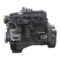
New Holland 667TA/EBF Repair Manual (150 pages)
Brand:
New Holland
| Category:
Engine
| Size: 11.2 MB
Table of Contents
Table of Contents
3
Chapter 1 Diagnostics
7
Table of Contents
7
Cnh- Est Diagnostic Tool
9
Troubleshooting
10
Engine Won't Start
10
Engine Overheats
11
Engine Lacks Power and Runs Erratically
12
Engine Exhaust Smoke Black or Dark Grey
13
Engine Exhaust Smoke Grey (Verging on White)
13
Engine Exhaust Smoke Light Blue
13
Engine Knocks Irregularly
14
Engine Stops
15
Excessive or Insufficient Oil Pressure
15
Excessive Fuel Consumption
15
Chapter 2 667Ta Engine Overhaul
17
Ta Engine Overhaul
19
Table of Contents
19
Engines
23
Coding of Source Engines
24
Engine Properties
24
General Engine Features
25
Crank Gear Components and Cylinder Assembly
27
Valve Gear - Cylinder Assembly
30
Torque Specifications
32
Special Tools
34
667Ta Engines
35
Description of Main Engine Components
36
Engine Block
36
Crankshaft
37
Crankshaft Oil Seals
37
Connecting Rods
38
Pistons
39
Egr Exhaust Gas Recirculation System
40
Camshaft
40
Valve Control
41
Cylinder Head Engines: 667TA/EBF - 667TA/EBD - 667TA/EED
42
Cylinder Head Engines: 667TA/EEG - 667TA/EEC
43
Cylinder Head Engine: 667TA/EDJ
44
Valves and Valve Seats
45
Valve Bridges
45
Engine Head Machining
46
Engine Flywheel
46
Accessory Equipment Drive
47
Engine Lubrication
48
Oil Cooler
49
Oil Pressure Control Valve
49
By-Pass Valve
49
Oil Pump
50
Oil Pan (Sump) Engines: 667TA/EEG- 667TA/EEC- 667TA/EBF- 667TA/EED- 667TA/EDJ
50
Oil Pan (Sump) Engines: 667TA/EED
51
667Ta/Ebd
51
Engine Oil Vapor Recirculation
52
Blow-By Recirculation
52
Engine Cooling
53
Water Pump
54
High Pressure Electronic Injection System (Common Rail)
55
Edc7Uc31 -Electronic Control Unit Operation
56
Engine Preheating Element Control
56
Phase Recognition
56
Injection Control
56
Injection Pressure Closed Loop Control
56
Pilot and Main Injection Advance Control
56
Idle Speed Control
56
Overheating Protection
56
Maximum Engine Speed Limiting
56
Cut off
56
Recover Strategies
57
Fuel Supply System
58
Fuel Supply System Diagram
59
Fuel Filter
60
Mechanical Supply Pump- Normal Operating Condition
61
Mechanical Supply Pump- Outlet Overpressure Condition
61
Fuel System Bleeding
62
High Pressure Pump Type CP3.3
63
High Pressure Pump Inside Structure
65
Operating Principal
66
Theory of Operation
67
Common Rail
68
Common Rail Pressure Relief Valve
69
Electro-Injector
70
Injection End
70
Electro-Injector
71
Pressure Limiter for Fuel Return
72
Location of the Main Electrical Components
73
EDC7UC31 Electronic Control Unit
74
Cabling Connector Pinout on Engine
75
Connector (A) Injectors Pinout Diagram
76
Connector (C) Sensors Pinout Diagram
76
Crankshaft Sensor
77
Camshaft Sensor
77
Boost Temperature - Pressure Sensor
78
Engine Oil Temperature - Pressure Sensor
78
Common Rail Fuel Pressure Sensor
79
Electro-Injectors
80
Intake Air Pre-Post Resistance Heater and Relay
81
Coolant Temperature Sensor
82
Fuel Temperature Sensor
83
High Pressure Pump - Pressure Regulator
84
Checking the Fuel System
85
Low Pressure Supply Test
85
Low -Pressure Pump
86
Test on the Pressure Relief Valve on the Common Rail
87
Test on Fuel Backflow from the Return
88
Engine Overhaul on the Bench
90
Disassembling the Engine
90
Checks and Specifications on Engine Crankcase
100
Checks and Measurements
100
Checking the Eccentric Lift and Bearing Surface
101
Bearings
101
Checking the Crankcase Cylinder Head Mating Surface
102
Camshaft Timing
103
Replacing the Cam Bearings
103
Tappets
103
Installing the Tappets and Camshaft
104
Crankshaft
105
Replacing the Oil Pump Drive Gears
107
Installing the Main Bearings
107
Measuring the Journal Assembly Play
107
Checking Crankshaft Shoulder Play
108
Connecting Rod-Piston Assembly
109
Measuring the Piston Diameter
110
Piston Pins
110
Conditions for Correct Pin/Piston Matching
111
Piston Rings
111
Connecting Rods
112
Bearings
113
Checking the Connecting Rods
113
Checking the Twisting
113
Checking the Flexing
114
Installing Connecting Rod-Piston Assembly Connecting Rod-Piston Coupling
114
Installing the Piston Rings
115
Installing the Connecting Rod-Piston Assemblies in the Cylinder Bores
115
Measuring Crank Pin Assembly Play
116
Checking Piston Protrusion
117
Timing Gear Case
117
Valve Timing
118
Flywheel Cover Case
119
Engine Flywheel
120
Replacing Engine Flywheel Ring Gear
120
Cylinder Head
125
Removing the Valves
125
Valves
126
Checking Cylinder Head Water Seal
126
Checking the Cylinder Head Mating Surface
126
Valve Guide
127
Valve Cleaning, Check and Grinding
127
Checking Assembly Play, and Valve Centering
127
Valve Seats
128
Valve Seat Reconditioning-Replacement
128
Valve Springs
130
Cylinder Head
130
Installing the Cylinder Head
131
Installing Injectors
131
Rods and Tappets
133
Rocker Arm Assembly
133
Locating Top Dead Center (TDC)
134
Valve Clearance Adjustment
134
Wiring Harness Connections to Engine
139
Chapter 3 Charging and Start-Up
141
Chapter 3 Charging and Start-Up
143
Table of Contents
143
Starter Motor
145
Quick Diagnosis
145
BOSCH 24 Volt - 4 KW Starter
146
ISKRA 24 Volt - 4 KW Starter
147
DENSO 24Volt - 7.8KW Starter
147
Alternator
148
Quick Diagnosis
148
BOSCH: NCBI 28 Volt 35-70 Amp
149
Advertisement
Advertisement
Related Products
New Holland 667TA/EEG
New Holland 667TA/EEC
New Holland 667TA/EED
New Holland 667TA/EBJ
New Holland 667TA/EDJ
New Holland 6640
New Holland 616
New Holland 617
New Holland 6500
New Holland 6510
New Holland Categories
Tractor
Farm Equipment
Excavators
Compact Loader
Lawn and Garden Equipment
More New Holland Manuals
Login
Sign In
OR
Sign in with Facebook
Sign in with Google
Upload manual
Upload from disk
Upload from URL