Sign In
Upload
Manuals
Brands
Motorola Manuals
Two-Way Radio
GP328 Plus
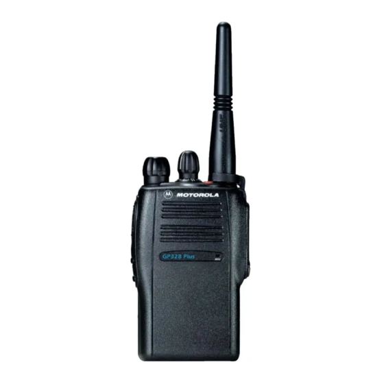
Motorola GP328 Plus Manuals
Manuals and User Guides for Motorola GP328 Plus. We have
1
Motorola GP328 Plus manual available for free PDF download: Service Manual
Motorola GP328 Plus Service Manual (206 pages)
Portable Radios
Brand:
Motorola
| Category:
Two-Way Radio
| Size: 8.04 MB
Table of Contents
Computer Software Copyrights
2
Document History
7
Safety Information
7
Compliance with Rf Exposure Standards
8
Operating Instructions
8
Approved Accessories
9
Additional Information
9
Medical Devices
9
Use of Communication Devices While Driving
10
Operational Warnings
10
Operational Cautions
11
Intrinsically Safe Radio Information
11
Do Not Substitute Options or Accessories
12
Table of Contents
13
Section 1 Introduction
19
Introduction
19
Scope of Manual
19
Warranty and Service Support
19
Warranty Period
19
After Warranty Period
19
Piece Parts
20
Technical Support
20
Further Assistance from Motorola
20
Service Aids
21
Section 2 Service Aids
21
Recommended Test Tools
21
Power up Self-Test
23
Section 3 Power up Self-Test
23
Error Codes
23
Controller Information
25
Section 4 Controller Information
25
Overview
25
Radio Power Distribution
25
Controller Board
26
General
26
Digital Architecture
27
Keypad
29
Troubleshooting Chart
30
Controller Board Diagrams
31
Controller Board Top View (PCB No. 8404051G07/G08)
31
Controller Board Top View (PCB No. 8404051G07/G08)
32
Controller Board Top View (PCB No. 8404051G09)
33
Controller Board Bottom View (PCB No.8404051G09)
34
Controller Schematics
35
Complete Controller Schematic Diagram
35
Controller ASFIC/ON_OFF Schematic Diagram
36
Controller Micro Processor Schematic Diagram
37
Controller Memory Schematic Diagram
38
Controller Audio Power Amplifier Schematic Diagram
39
Controller Parts List for VHF (for 8404051G07/G08 and 8404051G09)
40
8404051G09)
41
Controller Board Diagrams
42
Controller Board Top View (PCB No. 8404056G01)
42
Controller Board Bottom View (PCB No.8404056G01)
43
Controller Board Top View (PCB No. 8404056G02)
44
Controller Board Bottom View (PCB No. 8404056G02)
45
Controller Schematics
46
Complete Controller Schematic Diagram
46
Controller ASFIC/ON_OFF Schematic Diagram
47
Controller Micro Processor Schematic Diagram
48
Controller Memory Schematic Diagram
49
Controller Audio Power Amplifier Schematic Diagram
50
Controller Interface Schematic Diagram (for 8404056G01)
51
Controller Interface Schematic Diagram (for 8404056G02)
52
Controller Parts List for VHF (for 8404056G01/G02)
53
Controller Parts List for UHF 1, UHF 2 and 330Mhz (for 8404056G01/G02)
55
Section 5A
57
Model Chart and Test Specifications (136-174 Mhz)
57
Model Chart
57
Specifications (for GP328 Plus)
58
Specifications (for GP338 Plus/Gp338 XLS)
58
Transmitter
60
General
60
Receiver
62
Receiver Front-End
62
Receiver Back-End
63
Automatic Gain Control Circuit
64
Frequency Generation Circuitry
65
Synthesizer
66
VCO - Voltage Controlled Oscillator
67
Notes for All Schematics and Circuit Boards
69
Circuit Board/Schematic Diagrams and Parts List
71
VHF (136-174Mhz) Main Board Top Side PCB No. 8404055G05/G06/G07
71
VHF (136-174Mhz) Main Board Bottom Side PCB No. 8404055G05/G06/G07
72
VHF (136-174Mhz) Main Board Top Side PCB No. 8404055G09
73
VHF (136-174Mhz) Main Board Bottom Side PCB No. 8404055G09
74
VHF Controls and Switches Schematic Diagram (Sheet 2 of 2 for 8404055G09 PCB)
77
VHF Receiver Front End Schematic Diagram
78
VHF Receiver Back End Schematic Diagram
79
VHF Synthesizer Schematic Diagram
80
VHF Voltage Controlled Oscillator Schematic Diagram
81
VHF Transmitter Schematic Diagram
82
VHF Radio Parts List (RF Board)
83
Troubleshooting Charts
87
Troubleshooting Flow Chart for Controller
87
Troubleshooting Flow Chart for Receiver (Sheet 1
88
Troubleshooting Flow Chart for Receiver (Sheet 2
89
Troubleshooting Flow Chart for Transmitter
90
Troubleshooting Flow Chart for Synthesizer
91
Troubleshooting Flow Chart for VCO
92
Section 5B
93
Model Chart and Test Specifications (403-470 Mhz)
93
Model Chart
93
Specifications (for GP328 Plus)
94
Specifications (for GP338 Plus/Gp338 XLS)
94
Transmitter
96
General
96
Receiver
98
Receiver Front-End
98
Receiver Back-End
99
Automatic Gain Control Circuit
100
Frequency Generation Circuitry
101
Synthesizer
102
VCO - Voltage Controlled Oscillator
103
Notes for All Schematics and Circuit Boards
105
Circuit Board/Schematic Diagrams and Parts List
107
UHF (403-470Mhz) Main Board Top Side PCB No. 8404077G05/G06/G07
107
UHF (403-470Mhz) Main Board Bottom Side PCB No. 8404077G05/G06/G07
108
UHF (403-470Mhz) Main Board Top Side PCB No. 8404077G09
109
UHF (403-470Mhz) Main Board Bottom Side PCB No. 8404077G09
110
UHF Controls and Switches Schematic Diagram (Sheet 1
112
UHF Controls and Switches Schematic Diagram (Sheet 2 of 2 for 8404077G09 PCB)
112
UHF Receiver Front End Schematic Diagram
113
UHF Receiver Back End Schematic Diagram
114
UHF Synthesizer Schematic Diagram
115
UHF Voltage Controlled Oscillator Schematic Diagram
116
UHF Transmitter Schematic Diagram
117
UHF Band 1 Radio Parts List (RF Board)
118
Troubleshooting Charts
121
Troubleshooting Flow Chart for Controller
121
Troubleshooting Flow Chart for Receiver (Sheet 1
122
Troubleshooting Flow Chart for Receiver (Sheet 2
123
Troubleshooting Flow Chart for Transmitter
124
Troubleshooting Flow Chart for Synthesizer
125
Troubleshooting Flow Chart for VCO
126
Section 5C
127
Model Chart and Test Specifications (450-527 Mhz)
127
Model Chart
127
Specifications (for GP328 Plus)
128
Specifications (for GP338 Plus/Gp338 XLS)
128
Transmitter
130
General
130
Receiver
132
Receiver Front-End
132
Receiver Back-End
133
Automatic Gain Control Circuit
134
Frequency Generation Circuitry
135
Synthesizer
136
VCO - Voltage Controlled Oscillator
137
Notes for All Schematics and Circuit Boards
139
Circuit Board/Schematic Diagrams and Parts List
141
UHF Band 2 (450-527Mhz) Main Board Top Side PCB No. 8404102G03/G04/G05
141
UHF Band 2 (450-527Mhz) Main Board Bottom Side PCB No. 8404102G03/G04/G05
142
UHF Band 2 (450-527Mhz) Main Board Top Side PCB No. 8404102G07
143
UHF Band 2 (450-527Mhz) Main Board Bottom Side PCB No. 8404102G07
144
UHF Band 2 Controls and Switches Schematic Diagram (Sheet 1 of 2)
145
UHF Band 2 Controls and Switches Schematic Diagram (Sheet 2 of 2 for 8404102G07 PCB)
147
UHF Band 2 Receiver Front End Schematic Diagram
148
UHF Band 2 Receiver Back End Schematic Diagram
149
UHF Band 2 Synthesizer Schematic Diagram
150
UHF Band 2 Voltage Controlled Oscillator Schematic Diagram
151
UHF Band 2 Transmitter Schematic Diagram
152
UHF Band 2 Radio Parts List (RF Board)
153
Troubleshooting Charts
157
Troubleshooting Flow Chart for Controller
157
Troubleshooting Flow Chart for Receiver (Sheet 1
158
Troubleshooting Flow Chart for Transmitter
160
Troubleshooting Flow Chart for Synthesizer
161
Troubleshooting Flow Chart for VCO
162
Section 5D
163
Model Chart and Test Specifications (330-400 Mhz)
163
Model Chart
163
Specifications (for GP328 Plus)
164
Specifications (for GP338 Plus)
165
Transmitter
166
General
166
Receiver
168
Receiver Front-End
168
Receiver Back-End
169
Automatic Gain Control Circuit
170
Frequency Generation Circuitry
171
Synthesizer
172
VCO - Voltage Controlled Oscillator
173
Notes for All Schematics and Circuit Boards
175
Circuit Board/Schematic Diagrams and Parts List
177
330-400Mhz Main Board Top Side PCB No. 8404101G02/G03/G04
177
330-400Mhz Main Board Bottom Side PCB No. 8404101G02/G03/G04
178
330-400Mhz Main Board Top Side PCB No. 8404101G06
179
330-400Mhz Main Board Bottom Side PCB No. 8404101G06
180
330-400Mhz Controls and Switches Schematic Diagram (Sheet 2 of 2 for 8404101G06 PCB)
183
330-400Mhz Receiver Front End Schematic Diagram
184
330-400Mhz Receiver Back End Schematic Diagram
185
330-400Mhz Synthesizer Schematic Diagram
186
330-400Mhz Voltage Controlled Oscillator Schematic Diagram
187
330-400Mhz Transmitter Schematic Diagram
188
330-400Mhz Radio Parts List (RF Board)
189
Troubleshooting Charts
193
Troubleshooting Flow Chart for Controller
193
Troubleshooting Flow Chart for Receiver (Sheet 1
194
Troubleshooting Flow Chart for Transmitter
196
Troubleshooting Flow Chart for Synthesizer
197
Troubleshooting Flow Chart for VCO
198
Flex Layout/Schematic Diagrams and Parts Lists
199
Section 6 Flex Layout/Schematic Diagrams and Parts Lists
199
RF-Controller Interconnect Flex
199
Rev a
199
Rev B
199
Schematic for RF-Controller Interconnect Flex
200
Universal Connector Flex
201
GP328 Plus
201
GP338 Plus/Gp338 XLS
202
Schematic for Universal Connector Flex
203
GP328 Plus
203
GP338 Plus/Gp338 XLS
203
Parts List for Universal Connector Flex
204
GP328 Plus
204
GP338 Plus/Gp338 XLS
204
Advertisement
Advertisement
Related Products
Motorola GP328
Motorola GP644
Motorola Professional GP640
MOTOROLA RADIUS GP300
Motorola GP338
Motorola Professional GP680
Motorola GP380 Series
Motorola GP338 Plus
Motorola GP338 XLS
Motorola GP580 EX
Motorola Categories
Cell Phone
Two-Way Radio
Baby Monitor
Cordless Telephone
Radio
More Motorola Manuals
Login
Sign In
OR
Sign in with Facebook
Sign in with Google
Upload manual
Upload from disk
Upload from URL