Sign In
Upload
Manuals
Brands
Motorola Manuals
Portable Radio
EP350 Series
Motorola EP350 Series Manuals
Manuals and User Guides for Motorola EP350 Series. We have
4
Motorola EP350 Series manuals available for free PDF download: Service Manual, Basic Service Manual, User Manual
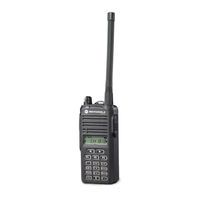
Motorola EP350 Series Service Manual (154 pages)
Brand:
Motorola
| Category:
Portable Radio
| Size: 9.59 MB
Table of Contents
Computer Software Copyrights
5
Safety Information
6
Document History
7
Table of Contents
9
Notations Used in this Manual
16
Chapter 1 Maintenance
19
Preventive Maintenance
19
Inspection
19
Cleaning
19
Safe Handling of CMOS and LDMOS
20
General Repair Procedures and Techniques
20
Table 1-1. Lead Free Solder Wire Part Number List
21
Table 1-2. Lead Free Solder Paste Part Number List
21
Chapter 2 Test Equipment, Service Aids, and Service Tools
23
Test Equipment
23
Table 2-1. Recommended Test Equipment
23
Service Aids
24
Table 2-2. Service Aids
24
Figure 2-1. Programming/Test Cable (PMDN4077_R)
25
Figure 2-2. Cloning Cable (PMDN4076_R)
25
Figure 2-3. Wiring of the Connectors
25
Chapter 3 DC Power Distribution
27
DC Regulation and Distribution
27
Figure 3-1. DC Power Distribution Block Diagram
27
Table 3-1. Voltage Regulators
28
Chapter 4 Controller Theory of Operation
29
RX Audio Circuit
29
Audio Processor IC (U102)
29
RX Audio Processing
29
Figure 4-1. RX Audio Circuit
29
RX Tone Pl/Digital PL Decode Filtering
30
Audio Amp
30
Internal and External Speaker
30
TX Audio Circuit
31
Figure 4-2. TX Audio Circuit
31
4-Order 4 Khz Low-Pass Filter (U501-C, D)
32
Audio Processor IC (U102)
32
TX Audio Processing
32
Tx Tone Pl/Digital PL Encode Filtering
32
MIC and External MIC
32
TX Audio Amplifier and 6 Order 3 Khz Low-Pass Filter
33
TX Modulation Adjustment
33
Microprocessor Circuitry
33
Memory Usage
33
Control and Indicator Interface
33
Interface to USB Programming
33
Storage of Customer-Specific Information
33
Table 4-1. Radio Memory Requirements
33
Sensing of VOX Operating
34
Microprocessor Power-On Reset Routine
34
Microprocessor 7.3728 Mhz Clock
34
Battery Indicator
34
Chapter 5 435 - 480 Mhz UHF2 Theory of Operation
35
Introduction
35
UHF2 Receiver
35
Figure 5-1. UHF2 Receiver Block Diagram
35
Receiver Back End
36
Receiver Front End
36
UHF2 Transmitter
37
Power Amplifier
37
Antenna Switch
37
Harmonic Filter
37
Figure 5-2. UHF2 Transmitter Block Diagram
37
Auto Power Control
38
UHF2 Frequency Generation Circuitry
38
Reference Oscillator (12.8 Mhz VCTCXO)
38
Figure 5-3. UHF2 Frequency Generation Unit Block Diagram
38
PLL IC Prescaler and Comparator
39
Voltage Doubler and Charge Pump
39
Loop Filter
39
Dual VCO
39
Keypad
40
Figure 5-4. Keypad Block Diagram
40
Chapter 6 UHF2 Troubleshooting Tables
41
Troubleshooting Table for Receiver (UHF2)
41
Table 6-1. Troubleshooting Table for Receiver (UHF2)
41
Troubleshooting Table for Synthesizer (UHF2)
42
Table 6-2. Troubleshooting Table for Synthesizer (UHF2)
42
Troubleshooting Table for Transmitter (UHF2)
43
Table 6-3. Troubleshooting Table for Transmitter (UHF2)
43
Troubleshooting Table for Board and IC Signals (UHF2)
44
Table 6-4. Troubleshooting Table for Board and IC Signals (UHF2)
44
Chapter 7 UHF2 Schematic Diagrams, Overlays, and Parts Lists
47
Introduction
47
Notes for All Schematics and Circuit Boards
47
Four Layer Circuit Board
49
Speaker and Microphone Schematic
49
Speaker and Microphone Parts List
49
Figure 7-1. Four-Layer Circuit Board: Copper Steps in Layer Sequence
49
Figure 7-2. Speaker and Microphone Schematic
49
Circuit Board/Schematic Diagram and Parts List (UHF2: 435-480 Mhz)
50
Figure 7-3. UHF2 (435-480 Mhz) Receiver Schematic Diagram
50
Figure 7-4. VCO and PLL Schematic Diagram
51
Figure 7-5. Transmitter Schematic Diagram
52
Figure 7-6. Microprocessor and Keypad Schematic Diagram
53
Figure 7-7. Audio Power Amplifier and External Audio Schematic Diagram
54
Figure 7-8. Switches and Battery Schematic Diagram
55
Figure 7-9. Transmitter Audio Filter and Sub-Tone Schematic Diagram
56
Figure 7-10. UHF2 (435-480 Mhz) Mainboard Top Side: PCB No. 8431BEACON200
57
Figure 7-11. UHF2 (435-480 Mhz) Mainboard Bottom Side: PCB No. 8431BEACON200
58
Figure 7-12. UHF2 (435-480 Mhz) Sub Circuit Board Top View: PCB No. 8421BEACON100
59
Figure 7-13. UHF2 (435-480 Mhz) Sub Circuit Board Bottom View: PCB No. 8421BEACON100
60
Figure 7-14. UHF2 (435-480 Mhz) Keypad Board: PCB No. 8422BEACON100
61
Parts List
62
Chapter 8 136 - 174 Mhz VHF Theory of Operation
73
Introduction
73
VHF Receiver
73
Figure 8-1. VHF Receiver Block Diagram
73
Receiver Back End
74
Receiver Front End
74
VHF Transmitter
75
Power Amplifier
75
Antenna Switch
75
Harmonic Filter
75
Figure 8-2. VHF Transmitter Block Diagram
75
Auto Power Control
76
VHF Frequency Generation Circuitry
76
Reference Oscillator (12.8 Mhz VCTCXO)
76
Figure 8-3. VHF Frequency Generation Unit Block Diagram
76
PLL IC Prescaler and Comparator
77
Voltage Doubler and Charge Pump
77
Loop Filter
77
Dual VCO
77
Keypad
78
Figure 8-4. Keypad Block Diagram
78
Chapter 9 VHF Troubleshooting Tables
79
Troubleshooting Table for Receiver (VHF)
79
Table 9-1. Troubleshooting Table for Receiver (VHF)
79
Troubleshooting Table for Synthesizer (VHF)
80
Table 9-2. Troubleshooting Table for Synthesizer (VHF)
80
Troubleshooting Table for Transmitter (VHF)
81
Table 9-3. Troubleshooting Table for Transmitter (VHF)
81
Troubleshooting Table for Board and IC Signals (VHF)
82
Table 9-4. Troubleshooting Table for Board and IC Signals (VHF)
82
Chapter 10 VHF Schematic Diagrams, Overlays, and Parts Lists
85
Introduction
85
Notes for All Schematics and Circuit Boards
85
Four Layer Circuit Board
87
Speaker and Microphone Schematic
87
Speaker and Microphone Parts List
87
Figure 10-1. Four-Layer Circuit Board: Copper Steps in Layer Sequence
87
Figure 10-2. Speaker and Microphone Schematic
87
Circuit Board/Schematic Diagram and Parts List (VHF: 136-174 Mhz)
88
Figure 10-3. VHF (136-174 Mhz) Receiver Schematic Diagram
88
Figure 10-4. VCO and PLL Schematic Diagram
89
Figure 10-5. Transmitter Schematic Diagram
90
Figure 10-6. Microprocessor and Keypad Schematic Diagram
91
Figure 10-7. Audio Power Amplifier and External Audio Schematic Diagram
92
Figure 10-8. Switches and Battery Schematic Diagram
93
Figure 10-9. Transmitter Audio Filter and Sub-Tone Schematic Diagram
94
Figure 10-10. Receiver Audio Filter and Sub-Tone Schematic Diagram
95
Figure 10-11. VHF (136-174 Mhz) Mainboard Top Side: PCB No. 8431BEACON400
96
Figure 10-12. VHF (136-174 Mhz) Mainboard Bottom Side: PCB No. 8431BEACON400
97
Figure 10-13. VHF (136-174 Mhz)Sub Circuit Board Top View: PCB No. 8421BEACON100
98
Figure 10-14. VHF (136-174 Mhz)Sub Circuit Board Bottom View: PCB No. 8421BEACON100
99
Figure 10-15. VHF (136-174 Mhz) Keypad Board: PCB No. 8422BEACON100
100
Parts List
101
Chapter 11 403 - 447 Mhz UHF1 Theory of Operation
111
Introduction
111
UHF1 Receiver
111
Figure 11-1. UHF1 Receiver Block Diagram
111
Receiver Back End
112
Receiver Front End
112
UHF1 Transmitter
113
Power Amplifier
113
Antenna Switch
113
Harmonic Filter
113
Figure 11-2. UHF1 Transmitter Block Diagram
113
Auto Power Control
114
UHF1 Frequency Generation Circuitry
114
Reference Oscillator (12.8 Mhz VCTCXO)
114
Figure 11-3. UHF1 Frequency Generation Unit Block Diagram
114
PLL IC Prescaler and Comparator
115
Voltage Doubler and Charge Pump
115
Loop Filter
115
Dual VCO
115
Keypad
116
Figure 11-4. Keypad Block Diagram
116
Chapter 12 UHF1 Troubleshooting Tables
117
Troubleshooting Table for Receiver (UHF1)
117
Table 12-1. Troubleshooting Table for Receiver (UHF1)
117
Troubleshooting Table for Synthesizer (UHF1)
118
Table 12-2. Troubleshooting Table for Synthesizer (UHF1)
118
Troubleshooting Table for Transmitter (UHF1)
119
Table 12-3. Troubleshooting Table for Transmitter (UHF1)
119
Troubleshooting Table for Board and IC Signals (UHF1)
120
Table 12-4. Troubleshooting Table for Board and IC Signals (UHF1)
120
Chapter 13 UHF1 Schematic Diagrams, Overlays, and Parts Lists
123
Introduction
123
Figure 13-1. Four-Layer Circuit Board: Copper Steps in Layer Sequence
125
Figure 13-2. Speaker and Microphone Schematic
125
Figure 13-3. UHF1 (403-447 Mhz) Receiver Schematic Diagram
126
Figure 13-4. VCO and PLL Schematic Diagram
127
Figure 13-5. Transmitter Schematic Diagram
128
Figure 13-6. Microprocessor and Keypad Schematic Diagram
129
Figure 13-7. Audio Power Amplifier and External Audio Schematic Diagram
130
Figure 13-8. Switches and Battery Schematic Diagram
131
Figure 13-9. Transmitter Audio Filter and Sub-Tone Schematic Diagram
132
Figure 13-10. UHF1 (403-447 Mhz) Mainboard Top Side: PCB No. 8431BEAUHF300
133
Figure 13-11. UHF1 (403-447 Mhz) Mainboard Bottom Side: PCB No. 8431BEAUHF300
134
Figure 13-12. UHF1 (403-447 Mhz) Sub Circuit Board Top View: PCB No. 8421BEACON100
135
Figure 13-13. UHF1 (403-447 Mhz) Sub Circuit Board Bottom View: PCB No. 8421BEACON100
136
Replacement Parts
147
Advertisement
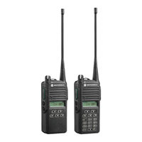
Motorola EP350 Series Basic Service Manual (118 pages)
Brand:
Motorola
| Category:
Portable Radio
| Size: 8.97 MB
Table of Contents
Computer Software Copyrights
5
Safety
6
Document History
7
Table of Contents
9
Notations Used in this Manual
15
Chapter 1 Model Charts and Test Specifications
17
Radio Model Information
17
Table 1-1. Radio Model Number (Example:mdh03Rdh8Aa7)
17
Model Chart for UHF2, 435-480 Mhz
18
Model Chart for VHF, 136-174 Mhz
19
Model Chart for UHF1, 403-447 Mhz
20
UHF2 Specifications
21
VHF Specifications
22
UHF1 Specifications
23
Chapter 2 Theory of Operation
25
Introduction
25
Major Assemblies
25
Receiver
25
Figure 2-1. Receiver Block Diagram
25
RX Back End
26
RX Front End
26
RX Squelch
27
Transmitter
28
Figure 2-2. Transmitter Block Diagram
28
Phase Lock Loop Synthesizer
29
Figure 2-3. PLL Synthesizer Block Diagram
29
RX Audio Circuit
30
Figure 2-4. RX Audio Block Diagram
30
TX Audio Circuit
31
Figure 2-5. TX Audio Block Diagram
31
Microcontroller
32
Power Supply
32
Chapter 3 Test Equipment, Service Aids, and Service Tools
33
Test Equipment
33
Table 3-2. Recommended Test Equipment
33
Service Aids
34
Table 3-3. Service Aids
34
Figure 3-1. Programming/Test Cable (PMDN4077_R)
35
Figure 3-2. Cloning Cable (PMDN4076_R)
35
Figure 3-3. Wiring of the Connectors
35
Chapter 4 Performance Checks
37
General
37
Power-Up Self Test
37
Lcd/Led/Button/Volume Knob Test Mode
37
Figure 4-4. LCD Indication
37
Table 4-4. Radio Operation in Test Mode
37
Chapter 5 Radio Programming and Tuning
41
Introduction
41
CPS Programming Setup
41
Radio-To-Radio Cloning
41
Figure 5-5. CPS Programming Setup
41
Radio Tuning Setup
42
Figure 5-6. Radio Tuning Setup
42
Initial Test Equipment Control Settings
43
Transmitter Alignment Options
43
Transmit High Power Tuning
43
Table 5-5. Initial Equipment Control Settings
43
Table 5-6. Transmit High/Low Power Level
43
Transmit Low Power Tuning
44
Figure 5-7. Tx High Power Window (High Power)
44
Transmit Modulation Tuning
45
Service Monitor Setting
45
Figure 5-8. Tx Low Power Window (Low Power)
45
Table 5-7. Transmit Modulation Tuning
45
Transmit 12.5 Khz Modulation Tuning
46
Transmit 25 Khz Modulation Tuning
47
Figure 5-9. Tx Modulation 12.5 Khz Window
47
Receiver Tuning
48
Service Monitor Setting
48
Figure 5-10. Tx Modulation 25 Khz Window
48
Table 5-8. Receiver Squelch Tuning
48
Receive 12.5 Khz-Band Normal Squelch Tuning
49
Receive 12.5 Khz-Band Tight Squelch Tuning
50
Figure 5-11. Rx 12.5 Khz-Band Normal Squelch Tuning Window
50
Receive 25 Khz-Band Normal Squelch Tuning
51
Figure 5-12. Rx 12.5 Khz-Band Tight Squelch Tuning Window
51
Receive 25 Khz-Band Tight Squelch Tuning
52
Figure 5-13. Rx 25 Khz-Band Normal Squelch Tuning Window
52
Utilities
53
Program Serial no
53
Figure 5-14. Rx 25 Khz-Band Tight Squelch Tuning Window
53
Figure 5-15. Program Radio Serial No. Window
53
Front Panel Programming
54
Introduction
54
Dealer and User Configurations
54
Switching between Dealer and User Configurations
54
Entering Programming Mode
55
Exiting Programming Mode
55
Accessing Front Panel Programming Mode Parameters
55
Editing Front Panel Programming Mode Parameters
56
Table 5-9. Front Panel Programming Mode Parameters
56
Factory Reset
63
Chapter 6 Maintenance - EP350 (Full Keypad Model)
65
Introduction
65
Preventive Maintenance
65
Inspection
65
Cleaning Procedures
65
Safe Handling of CMOS and LDMOS Devices
66
Repair Procedures and Techniques - General
67
Table 6-10. Lead Free Solder Wire Part Number List
67
Table 6-11. Lead Free Solder Paste Part Number List
67
Disassembling and Reassembling the Radio
70
Figure 6-16. Full Keypad Without Channel Knob Model
70
Radio Disassembly - Detailed
71
Front Housing from Chassis Disassembly
71
Figure 6-17. Battery and Antenna Removal
71
Figure 6-18. Knob Removal
71
Figure 6-19. Chassis Removal
72
Figure 6-20. Speaker Wire and Flexible Cable Connection
72
Figure 6-21. Speaker Wire Removal
73
Figure 6-22. Unlatch the Flexible Cable
73
Chassis Assembly Disassembly
74
Figure 6-23. Sub-Circuit Board and Accessory Bracket Removal
74
Front Circuit Board, Display Module and Keypad Disassembly
75
Figure 6-24. Main Circuit Board, Finger Strips, O-Ring and Battery Contact Seal Removal(UHF2)
75
Figure 6-25. Main Circuit Board, Finger Strips, O-Ring and Battery Contact Seal Removal(UHF1)
75
Speaker Disassembly
76
Figure 6-26. Front Circuit Board Removal
76
Figure 6-27. LCD and Keypad Removal
76
Radio Reassembly - Detailed
77
Speaker Reassembly
77
Figure 6-28. Speaker Removal
77
Figure 6-29. Speaker Reassembly
77
Front Circuit Board, Display Module and Keypad Reassembly
78
Figure 6-30. LCD and Keypad Reassembly
78
Figure 6-31. Front Circuit Board Reassembly
78
Chassis Assembly Reassembly
79
Figure 6-32. Main Circuit Board, Finger Strips, O-Ring and Battery Contact Seal Reassembly(UHF2)
79
Figure 6-34. Sub Circuit Board and Accessory Bracket Reassembly
80
Figure 6-33. Main Circuit Board, Finger Strips, O-Ring and Battery Contact Seal Reassembly(UHF1)
80
Chassis and Front Housing Reassembly
81
Torque List
81
Figure 6-35. Chassis Assembly and Front Housing Assembly Reassembly
81
Table 6-12. Torque Chart
81
Mechanical View and Parts List
82
EP350 (Full Keypad Without Channel Knob) Exploded View and Parts List
82
Figure 6-36. EP350 (Full Keypad Without Channel Knob)Radio Exploded View
82
Table 6-13. Parts List (Full Keypad Without Channel Knob)
83
Chapter 7 Maintenance - EP350 (Limited Keypad Model)
85
Introduction
85
Preventive Maintenance
85
Inspection
85
Cleaning Procedures
85
Safe Handling of CMOS and LDMOS Devices
86
Repair Procedures and Techniques - General
87
Table 7-14. Lead Free Solder Wire Part Number List
88
Table 7-15. Lead Free Solder Paste Part Number List
88
Disassembling and Reassembling the Radio
90
Figure 7-37. Limited Keypad Without Channel Knob Model
90
Radio Disassembly - Detailed
91
Front Housing from Chassis Disassembly
91
Figure 7-38. Battery and Antenna Removal
91
Figure 7-39. Knob Removal
92
Figure 7-40. Chassis Removal
92
Figure 7-41. Speaker Wire and Flexible Cable Connection
93
Figure 7-42. Speaker Wire Removal
93
Chassis Assembly Disassembly
94
Figure 7-43. Unlatch the Flexible Cable
94
Figure 7-44. Sub-Circuit Board and Accessory Bracket Removal
94
Figure 7-45. Main Circuit Board, Finger Strips, O-Ring and Battery Contact Seal Removal(UHF2)
95
Figure 7-46. Main Circuit Board, Finger Strips, O-Ring and Battery Contact Seal Removal (UHF1)
95
Front Circuit Board, Display Module and Keypad Disassembly
96
Figure 7-47. Front Circuit Board Removal
96
Figure 7-48. LCD and Keypad Removal
96
Speaker Disassembly
97
Radio Reassembly - Detailed
97
Speaker Reassembly
97
Figure 7-49. Speaker Removal
97
Front Circuit Board, Display Module and Keypad Reassembly
98
Figure 7-50. Speaker Reassembly
98
Figure 7-51. LCD and Keypad Reassembly
98
Chassis Assembly Reassembly
99
Figure 7-52. Front Circuit Board Reassembly
99
Figure 7-53. Main Circuit Board, O-Ring and Battery Contact Seal Reassembly(UHF2)
100
Figure 7-54. Main Circuit Board, Finger Strips, O-Ring and Battery Contact Seal Reassembly(UHF1)
100
Chassis and Front Housing Reassembly
101
Figure 7-55. Sub Circuit Board and Accessory Bracket Reassembly
101
Figure 7-56. Chassis Assembly and Front Housing Assembly Reassembly
101
Torque List
102
Mechanical View and Parts List
102
EP350 (Limited Keypad Without Channel Knob) Exploded View and Parts List
102
Figure 7-57. EP350 (Limited Keypad Without Channel Knob) - Exploded View
102
Table 7-16. Torque Chart
102
Table 7-17. Parts List (Limited Keypad Without Channel Knob)
103
Chapter 8 Troubleshooting Tables
105
Error Codes
105
Table 8-18. Error Code Display
105
Troubleshooting Table for Receiver
106
Troubleshooting Table for Transmitter
107
Appendix A Accessories
109
Audio Accessories
109
Belt Clip
110
Appendix B Warranty, Service Support, and Replacement Parts
111
Scope of Manual
111
Warranty
111
What this Warranty Covers and for How Long
111
General Provisions
111
Table B-1. Portable Radios and Product Accessories Warranty
111
B.1 Scope of Manual
111
How to Get Warranty Service
112
What this Warranty Does Not Cover
112
Patent and Software Provisions
113
Piece Parts
114
Basic Ordering
114
Motorola Online
114
Motorola Service Centers
114
B.2.6 Piece Parts
114
Glossary of Terms
115
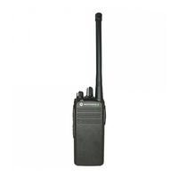
Motorola EP350 Series User Manual (86 pages)
Brand:
Motorola
| Category:
Two-Way Radio
| Size: 7.46 MB
Table of Contents
English
3
Table of Contents
3
Computer Software Copyrights
4
Safety
5
Product Safety and RF Exposure Compliance
5
Radio Overview
7
LED Colors
11
LCD Display and Icons
12
Programmable Buttons
13
Getting Started
15
Attaching and Removing the Antenna
15
Attaching and Removing the Battery
16
Attaching and Removing the Belt Clip
17
Charging the Battery
18
Charging Status
19
Scan
20
Deleting a Nuisance Scan Channel
20
Dual Tone Multiple Frequency (DTMF)
21
Features
21
Voice Selective Call and Call Alert
21
Receiving a Call Alert
22
Phone Mode
23
Voice Operated Transmit (VOX)
24
Voice Inversion Scrambling
25
Front Panel Programming Mode
26
Entering Front Panel Programming Mode
26
Exiting Front Panel Programming Mode
26
Assessing Front Panel Programming Mode Parameters
26
Main Menu
31
Warranty
35
Batteries and Chargers Warranty
38
Accessories
39
Español
43
Derechos de Autor de Software para Computadoras
44
Seguridad
45
Seguridad del Producto Ycumplimiento con la Exposición Rf
45
Visión General de la Radio
47
Colores del LED
51
Pantalla LCD E Iconos
52
Botones Programables
53
Inicio
55
Colocación y Extracción de la Antena
55
Colocación y Extracción de la Batería
56
Colocación y Extracción de Clip para Cinturón
57
Cómo Cargar la Batería
58
Estado de Carga
59
Exploración
60
Eliminación de un Canal de Exploración de Ruidos Molestos
60
(Dtmf)
61
Funciones de Frecuencia Múltiple de Tono Dual
61
Llamada Selectiva de Voz y Alerta de Llamada
61
Modo Teléfono
63
Transmisión Operada por Voz (VOX)
64
Codificación de la Inversión de Voz
65
Modo de Programación del Panel Frontal
66
Ingreso al Modo de Programación del Panel Frontal
66
Salida del Modo de Programación del Panel Frontal
66
Evaluación de Los Parámetros del Modo de Programación del Panel Frontal
66
Garantía
76
Accesorios
80
Advertisement
Motorola EP350 Series User Manual (60 pages)
Brand:
Motorola
| Category:
Two-Way Radio
| Size: 3.33 MB
Table of Contents
English
3
Table of Contents
3
Computer Software Copyrights
4
Safety
5
Product Safety and RF Exposure Compliance
5
Radio Overview
7
LED Colors
9
Battery Level Indicator
9
Programmable Buttons
10
Getting Started
12
Attaching and Removing the Antenna
12
Attaching and Removing the Battery
13
Attaching and Removing the Belt Clip
14
Charging the Battery
15
Charging Status
16
Scan
17
Deleting a Nuisance Scan Channel
17
Dual Tone Multiple Frequency (DTMF) Features
18
Receiving a Call Alert with Voice
18
Transmitting a PTT ID
18
MDC-1200 Features
19
Quik-Call II Features
20
Voice Operated Transmit (VOX)
21
Voice Inversion Scrambling
22
Warranty
23
Accessories
27
Español
31
Derechos de Autor de Software para Computadoras
32
Seguridad
33
Seguridad del Producto Ycumplimiento con la Exposición Rf
33
Visión General de la Radio
35
Colores del LED
37
Indicador del Nivel de Carga de la Batería
37
Botones Programables
38
Colocación y Extracción de la Antena
40
Inicio
40
Colocación y Extracción de la Batería
41
Colocación y Extracción de Clip para Cinturón
42
Cómo Cargar la Batería
43
Estado de Carga
44
Eliminación de un Canal de Exploración de Ruidos Molestos
45
Exploración
45
Funciones de Frecuencia Múltiple
46
Funciones MDC-1200
47
Funciones Llamada Rápida II
48
Transmisión Operada por Voz (VOX)
49
Codificación de la Inversión de Voz
50
Garantía
51
Accesorios
55
Advertisement
Related Products
Motorola EP450
Motorola EP10
Motorola EP150
Motorola EP350 MX
MOTOROLA E680 - Smartphone - GSM
Motorola EXORdisk II
Motorola ex560 xls
Motorola MOTOROKR E9
Motorola Moto e5 Plus
Motorola E201
Motorola Categories
Cell Phone
Two-Way Radio
Baby Monitor
Cordless Telephone
Radio
More Motorola Manuals
Login
Sign In
OR
Sign in with Facebook
Sign in with Google
Upload manual
Upload from disk
Upload from URL