Sign In
Upload
Manuals
Brands
Mitsubishi Manuals
Air Conditioner
PUHY-EP850
Mitsubishi PUHY-EP850 Manuals
Manuals and User Guides for Mitsubishi PUHY-EP850. We have
1
Mitsubishi PUHY-EP850 manual available for free PDF download: Service Handbook
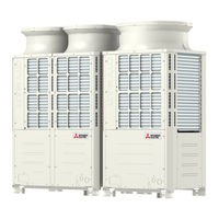
Mitsubishi PUHY-EP850 Service Handbook (298 pages)
Brand:
Mitsubishi
| Category:
Air Conditioner
| Size: 15.61 MB
Table of Contents
Chapter 1 Piping Work
8
Safety Precautions
2
Table of Contents
8
Preparation for Piping Work
12
Read before Servicing
12
Tool Preparation
13
Handling and Characteristics of Piping Materials, Refrigerant, and Refrigerant Oil
14
Piping Materials
14
Pipe Processing
16
Storage of Piping Materials
16
Characteristics of the New and Conventional Refrigerants
17
Refrigerant Oil
18
Working with Refrigerant Piping
19
Pipe Brazing
19
Air Tightness Test
20
Vacuum Drying
21
Refrigerant Charging
22
Chapter 2 Restrictions
24
System Configurations
26
Types and Maximum Allowable Length of Cables
27
Switch Settings
28
Address Settings List
29
M-NET Address Settings
29
Outdoor Unit Centralized Controller Switch Setting
30
Outdoor Unit Power Jumper Connector Connection
30
Room Temperature Detection Position Selection
30
Miscellaneous Settings
31
Start/Stop Control of Indoor Units
31
Various Control Methods Using the Signal Input/Output Connector on Outdoor Unit
32
Demand Control Overview
35
System Connection Example
37
Example System with an MA Remote Controller
39
Single Refrigerant System (Automatic Indoor/Outdoor Address Startup)
39
Single Refrigerant System with Two or more LOSSNAY Units
41
Grouped Operation of Units in Separate Refrigerant Circuits
43
System with a Connection of System Controller to Centralized Control Transmission Line
45
System with a Connection of System Controller to Indoor-Outdoor Transmission Line
47
Example System with an ME Remote Controller
49
System with a Connection of System Controller to Centralized Control Transmission Line
49
Example System with an MA and an ME Remote Controller
51
System with a Connection of System Controller to Centralized Control Transmission Line
51
2-10 Restrictions on Refrigerant Pipes
53
Restrictions on Refrigerant Pipe Length
53
Restrictions on Refrigerant Pipe Size
55
Chapter 3 Major Components, Their Functions and Refrigerant Circuits
58
External Appearance and Refrigerant Circuit Components of Outdoor Unit
60
External Appearance of Outdoor Unit
60
Outdoor Unit Refrigerant Circuits
62
Outdoor Unit Refrigerant Circuit Diagrams
65
Functions of the Major Components of Outdoor Unit
66
Functions of the Major Components of Indoor Unit
69
Chapter 4 Electrical Components and Wiring Diagrams
70
Outdoor Unit Circuit Board Arrangement
72
Outdoor Unit Control Box
72
Fan Box
73
Control Board
74
Outdoor Unit Circuit Board Components
74
M-NET Board (Transmission Power Supply Board)
75
INV Board
76
Fan Board
77
Noise Filter
78
Connect Board
79
Outdoor Unit Electrical Wiring Diagrams
80
Transmission Booster Electrical Wiring Diagrams
82
Chapter 5 Control
84
Dipswitch Functions and Factory Settings
86
Outdoor Unit Switch Functions and Factory Settings
86
Indoor Unit Switch Functions and Factory Settings
89
Remote Controller Switch Functions and Factory Settings
90
Initial Control
92
Outdoor Unit Control
92
Overview
92
Rotation Control
92
Startup Control
92
Refrigerant Bypass Control
93
Frequency Control
94
Defrost Operation Control
95
Refrigerant Recovery Control
97
Control at Initial Startup
98
Outdoor Unit Fan Control
98
Refrigerant Flow Control (Linear Expansion Valve 2)
98
Subcool Coil Control (Linear Expansion Valve 1)
98
Emergency Operation Mode
101
Demand Control
104
Operation Mode
104
Operation Flowcharts
105
Operation Sequence Flowchart
105
Actions Performed in Different Modes
107
Chapter 6 Test Run
110
Read before Test Run
112
Function/Specification Comparison
113
Local Remote Controller Selection Tips
113
MA and ME Remote Controller Functions and Specifications
113
Address Registration
114
Making the Group and Interlock Settings from an ME Remote Controller
114
Overview
114
Address Search
116
Address Deletion
117
Making Group and Interlock Settings from Another Remote Controller
117
Selecting Remote Controller Functions from an ME Remote Controller
118
MA Remote Controller (PAR-31MAA)
120
Making Interlock Settings from an MA Remote Controller
120
MA Remote Controller (PAR-21MAA)
121
MA Simple Remote Controller
123
Changing the Room Temperature Detection Position
126
MA Remote Controller (PAR-31MAA)
127
Test Run Method
127
MA Remote Controller (PAR-21MAA)
129
Checking the Refrigerant Charge During Operation
130
Evaluating and Adjusting Refrigerant Charge
130
Operation Characteristics and Refrigerant Charge
130
Refrigerant Overcharge and Undercharge
130
The Amount of Refrigerant to be Added
131
Refrigerant Charge Adjustment Mode
134
6-10 the Following Symptoms Are Normal
136
Single Unit (High COP Unit)
137
Standard Operation Data (Reference Data)
137
Dual Unit Combination (High COP Unit)
140
Triple Unit Combination (High COP Unit)
145
Chapter 7 Troubleshooting Using Error Codes
152
Error Code and Preliminary Error Code Lists
154
Error Code Definitions and Solutions: Codes [0 - 999]
157
Error Code [0403]
157
Error Code Definitions and Solutions: Codes [1000 - 1999]
158
Error Code [1102]
158
Error Code [1301]
159
Error Code [1302] (During Operation)
160
Error Code [1302] (at Startup)
161
Error Code [1500]
161
Error Code Definitions and Solutions: Codes [2000 - 2999]
162
Error Code [2500] (Models with a Drain Sensor)
162
Error Code [2500] (Models with a Float Switch)
163
Error Code [2502] (Models with a Drain Sensor)
164
Error Code [2502] (Models with a Float Switch)
165
Error Code [2503]
166
Error Code [2600]
167
Error Code [2601]
167
Error Code Definitions and Solutions: Codes [3000 - 3999]
168
Error Code [3121]
168
Error Code Definitions and Solutions: Codes [4000 - 4999]
169
Error Code [4102]
169
Error Code [4106]
170
Error Code [4109]
170
Error Code [4115]
171
Error Code [4116]
171
Error Code [4121]
172
Error Codes [4220, 4225, 4226] Detail Code 108
173
Error Codes [4220, 4225, 4226] Detail Code 109
175
Error Codes [4220, 4225, 4226] Detail Code 111
175
Error Code [4230]
176
Error Codes [4220, 4225, 4226] Detail Code 131
176
Error Code [4240]
177
Error Codes [4250, 4255, 4256] Detail Code 101
178
Error Code [4250] Detail Codes 106 and 107
179
Error Codes [4250, 4255, 4256] Detail Code 104
180
Error Code [4260]
181
Error Codes [4250, 4255, 4256] Detail Code 105
181
Error Code Definitions and Solutions: Codes [5000 - 5999]
182
Error Codes [5101, 5102, 5103 5104]
182
Error Codes [5102, 5103, 5104, 5105, 5106, 5107]
183
Error Code [5110]
184
Error Code [5201]
184
Error Code [5301] Detail Code 115
185
Error Code [5301] Detail Code 117
185
Error Code [5301] Detail Code 119
186
Error Code [5301] Detail Code 120
186
Error Codes [5305, 5306] Detail Code 132
187
Error Codes [5305, 5306] Detail Code 133
187
Error Code [5701]
188
Error Codes [5305, 5306] Detail Code 134
188
Error Code Definitions and Solutions: Codes [6000 - 6999]
189
Error Code [6201]
189
Error Code [6202]
189
Error Code [6600]
190
Error Code [6601]
190
Error Code [6602]
191
Error Code [6603]
192
Error Code [6606]
192
Error Code [6607] Error Source Address = Outdoor Unit (OC)
193
Error Code [6607] Error Source Address = Indoor Unit (IC)
194
Error Code [6607] Error Source Address = LOSSNAY (LC)
195
Error Code [6607] Error Source Address = ME Remote Controller
196
Error Code [6607] Error Source Address = System Controller
197
Error Code [6607] All Error Source Addresses
198
Error Code [6607] no Error Source Address
199
Error Code [6608]
200
Error Code [6831]
201
Error Code [6832]
202
Error Code [6833]
203
Error Code [6834]
204
Error Code Definitions and Solutions: Codes [7000 - 7999]
205
Error Code [7100]
205
Error Code [7101]
206
Error Code [7102]
207
Error Code [7105]
208
Error Code [7106]
208
Chapter 8 Troubleshooting Based on Observed Symptoms
214
MA Remote Controller Problems
216
The LCD Does Not Light up
216
The LCD Momentarily Lights up and then Goes off
217
HO" and "PLEASE WAIT" Do Not Go off the Screen
218
Air Conditioning Units Do Not Operate When the on Button Is Pressed
219
ME Remote Controller Problems
220
The LCD Does Not Light up
220
The LCD Momentarily Lights up and then Goes off
221
HO" Does Not Go off the Screen
222
88" Appears on the LCD
223
Refrigerant Control Problems
224
Units in the Cooling Mode Do Not Operate at Expected Capacity
224
Units in the Heating Mode Do Not Operate at Expected Capacity
226
Outdoor Units Stop at Irregular Times
228
Checking Transmission Waveform and for Electrical Noise Interference
229
M-Net
229
MA Remote Controller
231
Comparing the High-Pressure Sensor Measurement and Gauge Pressure
232
High-Pressure Sensor Configuration (63HS1)
232
Pressure Sensor Circuit Configuration and Troubleshooting Pressure Sensor Problems
232
Comparing the Low-Pressure Sensor Measurement and Gauge Pressure
233
Low-Pressure Sensor Configuration (63LS)
233
Troubleshooting Solenoid Valve Problems
234
Troubleshooting Outdoor Unit Fan Problems
236
General Overview on LEV Operation
237
Troubleshooting LEV Problems
237
Possible Problems and Solutions
240
Coil Removal Instructions
241
Inverter-Related Problems and Solutions
243
Troubleshooting Inverter Problems
243
Checking the Compressor for Ground Fault and Coil Resistance Problems
245
Checking the Inverter Board Error Detection Circuit
245
Checking the Inverter for Damage at No-Load
245
Checking the Fan Board Error Detection Circuit at no Load
246
Checking the Fan Motor for Ground Fault and Coil Resistance Problems
246
Checking the Inverter for Damage During Compressor Operation
246
Checking the Fan Inverter for Damage at no Load
247
Checking the Fan Inverter for Damage with Load
248
Checking the Installation Conditions
248
Solutions for the Main Earth Leakage Breaker Trip
249
Solutions for the Main No-Fuse Breaker Trip
249
Simple Check on Inverter Circuit Components
250
Troubleshooting Problems with IGBT Module
250
8-10 Control Circuit
252
Control Power Supply Function Block
252
Indoor Unit
253
Troubleshooting Problems with Outdoor Unit Transmission Power Supply Circuit
254
8-11 Measures for Refrigerant Leakage
255
8-12 Compressor Replacement Instructions
257
Troubleshooting Problems Using the LED Status Indicators on the Outdoor Unit
259
Chapter 9 Led Status Indicators on the Outdoor Unit Circuit Board
260
How to Read the LED
262
LED Status Indicators
262
Initial LED Display
263
Clock Memory Function
264
LED Status Indicators Table
265
Advertisement
Advertisement
Related Products
Mitsubishi PUHY-EP800
Mitsubishi PUHY-EP300
Mitsubishi PUHY-EP350
Mitsubishi PUHY-EP450YKM-A
Mitsubishi PUHY-EP450YSKM-A
Mitsubishi PUHY-EP600
Mitsubishi PUHY-EP650YSKM-A
Mitsubishi PUHY-EP550
Mitsubishi PUHY-EP700
Mitsubishi PUHY-EP750
Mitsubishi Categories
Air Conditioner
Controller
Projector
Automobile
Engine
More Mitsubishi Manuals
Login
Sign In
OR
Sign in with Facebook
Sign in with Google
Upload manual
Upload from disk
Upload from URL