Sign In
Upload
Manuals
Brands
Liebert Manuals
Switch
Static Transfer Switch 2
Liebert Static Transfer Switch 2 Manuals
Manuals and User Guides for Liebert Static Transfer Switch 2. We have
2
Liebert Static Transfer Switch 2 manuals available for free PDF download: User Manual, Installation, Operation & Maintenance Manual
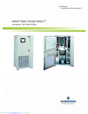
Liebert Static Transfer Switch 2 User Manual (152 pages)
100-1000A, 50/60Hz
Brand:
Liebert
| Category:
Switch
| Size: 5.83 MB
Table of Contents
Table of Contents
3
Important Safety Instructions
9
Save These Instructions
9
Overview of Manual
10
1 Safety Precautions
11
2 Unpacking and Inspections
12
External Inspections
12
Unloading and Handling
12
Handling Considerations
13
Unit Preparation
13
Internal Inspections
13
3 Location Considerations
14
Recommended Minimum Service Clearances
14
Heat Output
14
Operating Environment
14
Table 1 Heat Output
14
Altitude
15
Figure 1 Recommended Derating for High Altitude Operation
15
Figure 2 Maximum Ambient Temperature for Full Load Operation at Higher Altitudes
15
4 Locating the Liebert Sts2
16
Leveling and Anchoring the Unit to the Floor
16
Leveling of the Static Switch Without Anchoring
16
Leveling and Anchoring the Static Switch Using Floor Stand
16
5 Power and Control Wiring
17
Input and Output Power Connections
17
Input Junction Box Installation-Optional
18
Figure 3 Typical Static Transfer Switch One-Line Diagram
18
Table 2 Input/Output Conduit Plate Specifications
18
Table 3 Input Junction Box Dimensions
19
Table 3 Table
19
Table 4 Input Junction Box Terminal Wire Size Range
19
System Grounding
20
Control Wiring Connections
20
Figure 4 Typical One-Line Diagram of Two Pdus and a Static Transfer Switch
20
Remote Source Selection Wiring
21
Power Supply
21
Table 5 Remote Source Selection Terminal Block
21
Table 6 Terminal Block 1 and Terminal Block 2 Wire Connections
21
6 Options
22
Programmable Relay Board
22
Optimized Transfer
22
Table 7 Programmable Relay Board Pinout
22
Distribution Cabinet with I-Line Panelboard-100-600A Units Only
23
Input Contact Isolator Board
23
Comms Board
23
Liebert Intellislot ® Web/485 Card with Adapter
23
LED Display
24
Remote Source Selection
24
Key Lockout Switch
24
Redundant Output Breaker
24
Input Junction Boxes and Cables
25
Seismic Floor Anchors
25
Seismic Floor Stand
25
7 Installation Drawings
26
Figure 5 Outline Drawing: 100 - 250 Amp Liebert STS2
26
Figure 6 Outline Drawing: 400 - 600 Amp Liebert STS2
27
Figure 7 Outline Drawing: 800 - 1000 Amp Liebert STS2
28
Figure 8 Outline Drawing: 100 - 250Amp Liebert STS2 with a Key Lockout Switch Option
29
Figure 9 Outline Drawing: 400 - 600 Amp Liebert STS2 with a Key Lockout Switch Option
30
Figure 10 Outline Drawing: 800 - 1000 Amp Liebert STS2 with the Key Lockout Switch Option
31
Figure 11 Seismic Anchor Drawing: 100 - 250 Amp Liebert STS2
32
Figure 12 Seismic Anchor Drawing: 400 - 600 Amp Liebert STS2
33
Figure 13 Seismic Anchor Drawing: 800 - 1000 Amp Liebert STS2
34
Figure 14 Electrical Field Connections Drawing: 100 - 250 Amp Liebert STS2 with Single
35
Figure 15 Electrical Field Connections Drawing: 100 - 250 Amp Liebert STS2 with Dual
36
Figure 16 Electrical Field Connections Drawing: 400 - 600 Amp Liebert STS2 with Single
37
Figure 17 Electrical Field Connections Drawing: 400 - 600 Amp Liebert STS2 with Dual
38
Figure 18 Electrical Field Connections Drawing: 800 - 1000 Amp Liebert STS2 with Single
39
Figure 19 Electrical Field Connections: 800 - 1000 Amp Liebert STS2 with Dual Output Breakers
40
Figure 20 Liebert STS2 Non-Automatic Circuit Breaker Schedule
41
Figure 21 Control Connection Location Diagram: 100 - 600 Amp Liebert STS2
42
Figure 22 Control Connection Location Diagram: 800 - 1000 Amp Liebert STS2
43
Figure 23 Control Wiring for Remote Source Selection Option
44
Figure 24 Control Wiring for the Programmable Relay Board Option
45
Figure 25 Control Wiring for the Input Contact Isolator Board Option
46
Figure 26 Control Wiring for Comms Board
47
Figure 27 Control Wiring for the Liebert Intellislot Web/485 Card with Adapater
48
Figure 28 Control Wiring for the RS-232 Port
49
Figure 29 Outline Drawing for Input Junction Box
50
Figure 30 Color LCD Touch Screen Display
51
Figure 31 LED Display
52
Figure 32 Installation Drawing, Seismic Floor Stand 100-250A
53
Figure 33 Installation Drawing, Seismic Floor Stand 100-250A
54
Figure 34 Installation Drawing, Seismic Floor Stand 100-250A
55
Figure 35 Installation Drawing, Seismic Floor Stand 100-250A
56
Figure 36 Installation Drawing, Seismic Floor Stand 400-600A
57
Figure 37 Installation Drawing, Seismic Floor Stand 400-600A
58
Figure 38 Installation Drawing, Seismic Floor Stand 400-600A
59
Figure 39 Installation Drawing, Seismic Floor Stand 400-600A
60
Figure 40 Installation Drawing, Seismic Floor Stand 800-1000A
61
Figure 41 Installation Drawing, Seismic Floor Stand 800-1000A
62
Figure 42 Installation Drawing, Seismic Floor Stand 800-1000A
63
Figure 43 Installation Drawing, Seismic Floor Stand 800-1000A
64
8 Introduction to Liebert Sts2 Operations
65
System Description
65
Redundancy
65
Reliability and Agency Requirements
66
Factory Backup and Service Assistance
66
Modes of Operation
66
Normal (Preferred Source)
66
Transfer
66
Transfer Inhibit
66
Bypass
67
Operator Controls
67
Figure 44 Liebert STS2 Touch Screen Display
67
9 Theory of Operation
68
General Description
68
Liebert STS2 Static Transfer Switch
68
Source Transfer
68
Automatic Transfer/Retransfer
68
Emergency Transfer
69
Load Current Transfer Inhibit
69
SCR Failure
69
On/Off Sequence
69
Detailed Component Description
69
Controls
69
Circuit Breakers
70
Scrs
70
Logic Modules
71
Audible Alarm
71
Port
71
10 Operating Instructions for the Touch Screen Interface
72
Normal System Turn-On
73
Figure 45 Liebert STS2 Touch Screen Display
73
Manual Transfer / Preferred Source Selection
74
Figure 46 Source Transfer Screen
74
Enabling Remote Source Selection
75
Maintenance Bypass
75
Figure 47 Gate Board Viewing Slot Locations
76
Bypass Procedures for Source 1
77
Bypass Procedures for Source 2
78
Normal System Shutdown
78
10.5.1 Shutdown in Static Transfer Switch Mode
78
10.5.2 Shutdown in Maintenance Bypass Mode
78
11 Alarm and Faults
79
Event Mask
79
Event and History Logs
80
11.2.1 Event Log
80
11.2.2 History Log
80
Alarm Notes
81
List of Messages
81
Table 8 Event Messages
82
Interfaces
84
C Ommunication I Nterfaces
84
Using the RS-232 Port
84
Connecting and Using a Terminal
85
Table 9 Terminal Commands
85
Configuring the Liebert STS2 Via the Terminal
86
Table 10 Value Types
87
Table 11 Group Settings and Values
87
Setting Bitpacked Options with the Terminal
89
Table 12 Binary-Hexadecimal Conversions
90
Setting Event Masks with the Terminal
91
13 Liebert Sts2 Touch Screen Display
93
Display Overview
93
Figure 48 Liebert STS2 Touch Screen Display
93
Menu Overview
94
Figure 49 Menus
94
Figure 50 Keyboard and Keypad Displays
94
13.2.1 Security
95
Figure 51 Key Lockout Switch
95
MIMIC Display
96
Event Controls
96
Event Display
96
Menu Bar
96
Configuration Menu
96
Figure 52 Event Mask Dialog Box
97
Figure 53 User Settings Dialog Box
98
Figure 54 Source Setpoints
99
Table 13 Sepoint Parameters
99
Figure 55 Comm Options Dialog Box
101
Figure 56 Modem Dialog Box
102
Figure 57 Input Contact Isolator Dialog Box
104
Table 14 Standard Settings for Programmable Relays
105
Figure 58 Programmable Relay Board Dialog Box
106
Figure 59 System Options
107
13.6.2 Logs
109
Figure 60 Event Log
109
Figure 61 History Log
109
Source Transfers
110
Startup Procedure
110
Bypass Procedure
110
13.6.6 Help
110
13.6.7 Logo
110
Cleaning the LCD Touch Screen
110
14 O Lsts2 Led D
111
Perating the
111
O Perating the L Iebert Sts2 Led D Isplay
111
Leds and Buttons and Key Lockout Switch
111
Front Panel Controls
111
Figure 62 LED Display
111
LED and Push Button Description
112
Table 15 LED and Push Button Description
112
Event Controls
113
Key Lockout Switch
113
Operations
113
Normal System Turn on
113
Figure 63 Key Lockout Switch
113
Manual Transfer / Preferred Source Selection
114
Maintenance Bypass
116
Normal System Shutdown
118
15 Specifications
119
System Configuration
119
15.1.1 Frequency
119
Input/Output Voltage
119
System Current Ratings
119
Table 16 Input/Output Voltage
119
Table 17 System Current Ratings
119
15.1.4 Grounding
120
Electrical Requirements
120
Input Surge Suppression
120
Response Time
120
Environmental Requirements
120
Table 18 Electrical Requirements
120
Table 19 Unit Short Circuit Withstand Capability
120
System Components
121
Frame and Enclosure
121
Casters, Leveling and Seismic Anchoring
121
15.2.3 Cooling
121
Table 20 Frame Sizes
121
15.2.4 Access
122
Circuit Breakers
122
Cable Entrance
122
15.2.7 Doors
122
Color Graphical Display or LED Display
122
15.2.9 RS-232 Port
123
Terminal Port Connections
123
Table 21 MTA Plug Pinout
123
Table 22 DB9 Pinout
123
Interface Parameters
124
Maintenance Bypass
124
Fuseless Design
124
15.2.14 Options
124
Table 23 RS-232 Settings
124
16 Event Message Help Text
125
17 Maintenance
146
Proper Tightening of Nuts and Bolts
146
Testing the Liebert STS2
146
Changing the Air Filter
146
Table 24 Torque Tightening
146
Support Information
147
Programmable Relay Board Settings Record
148
Input Contact Isolator Settings
150
Advertisement
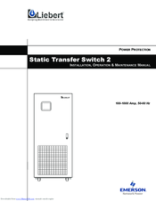
Liebert Static Transfer Switch 2 Installation, Operation & Maintenance Manual (150 pages)
100-1000 Amp, 50-60 Hz
Brand:
Liebert
| Category:
Switch
| Size: 2.57 MB
Table of Contents
Table of Contents
3
List of Figures
9
List of Tables
11
Important Safety Instructions
13
Overview of Manual
14
Support Information
15
Programmable Relay Board Settings Record
15
Input Contact Isolator Settings Record
17
1 Safety Precautions
19
2 Unpacking and Inspections
20
External Inspections
20
Unloading and Handling
20
Handling Considerations
21
Unit Preparation
21
Internal Inspections
21
3 Location Considerations
22
Recommended Minimum Service Clearances
22
Heat Output
22
Operating Environment
22
Table 1 Heat Output
22
Altitude
23
Figure 1 Recommended Derating for High Altitude Operation
23
Figure 2 Maximum Ambient Temperature for Full Load Operation at Higher Altitudes
23
Table 2 Altitude Conversion-Feet to Meters
23
4 Locating the Sts2
24
Leveling and Anchoring the Unit to the Floor
24
Leveling of the Static Switch Without Anchoring
24
5 Power and Control Wiring
25
Input and Output Power Connections
25
Input Junction Box Installation (Optional)
26
Figure 3 Typical Static Transfer Switch One-Line Diagram
26
Table 3 Input/Output Conduit Plate Specifications
26
System Grounding
27
Table 4 Input Junction Box Dimensions
27
Table 5 Input Junction Box Terminal Wire Size Range
27
Control Wiring Connections
28
Remote Source Selection Wiring
28
Figure 4 Typical One-Line Diagram of Two Pdus and a Static Transfer Switch
28
Power Supply
29
Table 6 Remote Source Selection Terminal Block
29
Table 7 Terminal Block 1 and Terminal Block 2 Wire Connections
29
6 Options
30
Programmable Relay Board
30
Table 8 Programmable Relay Board Pinout
30
Input Contact Isolator Board
31
Comms Board
31
Internal Modem
31
Network Interface Card (NIC)
32
Remote Source Selection
32
Key Lockout Switch
32
Redundant Output Breaker
32
Input Junction Boxes and Cables
33
Seismic Floor Anchors
33
7 Installation Drawings
35
Figure 5 Outline Drawing: 100 - 250 Amp STS2
35
Figure 6 Outline Drawing: 400 - 600 Amp STS2
36
Figure 7 Outline Drawing: 800 - 1000 Amp STS2
37
Figure 8 Outline Drawing: 100 - 250 Amp STS2 with a Key Lockout Switch Option
38
Figure 9 Outline Drawing: 400 - 600 Amp STS2 with a Key Lockout Switch Option
39
Figure 10 Outline Drawing: 800 - 1000 Amp STS2 with the Key Lockout Switch Option
40
Figure 11 Seismic Anchor Drawing: 100 - 250 Amp STS2
41
Figure 12 Seismic Anchor Drawing: 400 - 600 Amp STS2
42
Figure 13 Seismic Anchor Drawing: 800 - 1000 Amp STS2
43
Figure 14 Electrical Field Connections Drawing: 100 - 250 Amp STS2 with Single Output Breaker
44
Figure 15 Electrical Field Connections Drawing: 100 - 250 Amp STS2 with Dual Output Breakers
45
Figure 16 Electrical Field Connections Drawing: 400 - 600 Amp STS2 with Single Output Breaker
46
Figure 17 Electrical Field Connections Drawing: 400 - 600 Amp STS2 with Dual Output Breakers
47
Figure 18 Electrical Field Connections Drawing: 800 - 1000 Amp STS2 with Single Output Breaker
48
Figure 19 Electrical Field Connections: 800 - 1000 Amp STS2 with Dual Output Breakers
49
Figure 20 Circuit Breaker Schedule
50
Figure 21 Control Connection Location Diagram: 100 - 600 Amp STS2
51
Figure 22 Control Connection Location Diagram: 800 - 1000 Amp STS2
52
Figure 23 Control Wiring for Remote Source Selection Option
53
Figure 24 Control Wiring for the Programmable Relay Board Option
54
Figure 25 Control Wiring for the Input Contact Isolator Board Option
55
Figure 26 Control Wiring for Comms Board (See Figure 27 on Page 45 for Internal Modem Wiring)
56
Figure 27 Control Wiring for the Internal Modem Option
57
Figure 28 Control Wiring for the Network Interface Card (NIC) Option
58
Figure 29 Control Wiring for the RS-232 Port
59
Figure 30 Outline Drawing for Input Junction Box
60
Figure 31 Color LCD Touch Screen Display
61
8 Introduction to Sts2 Operations
63
System Description
63
Redundancy
63
Reliability and Agency Requirements
64
Factory Backup and Service Assistance
64
Modes of Operation
64
Normal (Preferred Source)
64
Transfer
64
Transfer Inhibit
65
Bypass
65
Operator Controls
65
Figure 32 STS2 Touch Screen Display
65
9 Theory of Operation
66
General Description
66
STS2 Static Transfer Switch
66
Source Transfer
66
Automatic Transfer/Retransfer
66
Emergency Transfer
67
Load Current Transfer Inhibit
67
SCR Failure
67
On/Off Sequence
67
Detailed Component Description
67
Controls
67
Circuit Breakers
68
Scrs
69
Logic Modules
69
Audible Alarm
69
Port
69
10 Operating Instructions for the Touch Screen Interface
70
Normal System Turn-On
70
Manual Transfer / Preferred Source Selection
71
Figure 33 STS2 Touch Screen Display
71
Figure 34 Source Transfer Screen
72
Enabling Remote Source Selection
73
Maintenance Bypass
73
Bypass Procedures for Source 1
74
Figure 35 Gate Board Viewing Slot Locations
74
Bypass Procedures for Source 2
75
Normal System Shutdown
76
Shutdown in Static Transfer Switch Mode
76
Shutdown in Maintenance Bypass Mode
76
11 Alarm and Faults
77
Event Mask
77
Event and History Logs
78
Event Log
78
History Log
78
Alarm Notes
79
List of Messages
79
Table 9 Event Messages
80
12 Communication Interfaces
82
Using the RS-232 Port
82
Connecting and Using a Terminal
83
Configuring the STS2 Via the Terminal
84
Table 10 Terminal Commands
84
Table 11 Value Types
85
Table 12 Group Settings and Values
85
Setting Bitpacked Options with the Terminal
86
Table 13 Binary-Hexidecimal Conversions
88
Setting Event Masks with the Terminal
89
13 Sts2 Touch Screen Display
91
Display Overview
91
Figure 36 STS2 Touch Screen Display
91
Menu Overview
92
Figure 37 Menus
92
Figure 38 Keyboard and Keypad Displays
92
Figure 39 Key Lockout Switch
93
Security
93
MIMIC Display
94
Event Controls
94
Event Display
94
Menu Bar
94
Configuration Menu
94
Figure 40 Event Mask Dialog Box
95
Figure 41 User Settings Dialog Box
96
Figure 42 Source Set Points
97
Table 14 Set Point Parameters
97
Figure 43 Comm Options Dialog Box
100
Figure 44 Modem Dialog Box
101
Figure 45 Input Contact Isolator Dialog Box
103
Figure 46 Programmable Relay Board Dialog Box
104
Table 15 Standard Settings for Programmable Relays
104
Figure 47 System Options
106
Logs
107
Figure 48 Event Log
107
Source Transfers
108
Startup Procedure
108
Bypass Procedure
108
Figure 49 History Log
108
Help
109
Logo
109
Cleaning the LCD Touch Screen
109
14 Operating the Led Display Sts2
111
Leds and Buttons and Key Lockout Switch
111
Front Panel Controls
111
Event Controls
112
LED Definitions
113
Table 16 Leds-Defined
113
Button Definitions
114
Key Lockout Switch
114
Table 17 Push Button Switches-Defined
114
Operations
115
Normal System Turn-On
115
Manual Transfer / Preferred Source Selection
116
Maintenance Bypass
116
Normal System Shutdown
118
15 Specifications
119
System Configuration
119
Frequency
119
Input/Output Voltage
119
System Current Ratings
119
Table 18 Input/Output Voltage
119
Table 19 System Current Ratings
119
Grounding
120
Electrical Requirements
120
Input Surge Suppression
120
Response Time
120
Environmental Requirements
120
Table 20 Electrical Requirements
120
Table 21 Unit Short Circuit Withstand Capability
120
System Components
121
Frame and Enclosure
121
Castors, Leveling and Seismic Anchoring
121
Cooling
121
Table 22 Frame Sizes
121
Access
122
Circuit Breakers
122
Cable Entrance
122
Doors
122
Color Graphical Display or LED Display
123
Port
123
Terminal Port Connections
123
Table 23 MTA Plug Pinout
123
Table 24 DB9 Pinout
123
Interface Parameters
124
Maintenance Bypass
124
Fuseless Design
124
Options
124
Table 25 RS-232 Settings
124
RS-232 Interface Parameters
124
16 Vent Essage Elp Ext
125
Event Message Help Text
125
17 0 Maintenance
147
Table 26 Torque Tightening
147
M Aintenance
147
Proper Tightening of Nuts and Bolts
147
Testing the Sts
147
Changing the Air Filter
147
Contacting Liebert
148
Advertisement
Related Products
Liebert Liebert Static Transfer Switch
Liebert SmartSwitchTM
Liebert SmartSwitch
Liebert SSWITCH2-25A
Liebert SSWITCH2-32A
Liebert STS2
Liebert UPStation S3
Liebert SGH Steam
Liebert SQH 023
Liebert MATRIX S CQH016
Liebert Categories
UPS
Air Conditioner
Power Supply
Surge Protector
Chiller
More Liebert Manuals
Login
Sign In
OR
Sign in with Facebook
Sign in with Google
Upload manual
Upload from disk
Upload from URL