Sign In
Upload
Manuals
Brands
Kubota Manuals
Excavators
u15-3
Kubota u15-3 Manuals
Manuals and User Guides for Kubota u15-3. We have
1
Kubota u15-3 manual available for free PDF download: Workshop Manual
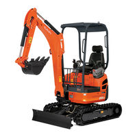
Kubota u15-3 Workshop Manual (213 pages)
Brand:
Kubota
| Category:
Excavators
| Size: 11.74 MB
Table of Contents
Table of Contents
5
Product Engineering Section
5
Developing Concept and Feature
7
Main Specifications
7
Objective and Concept of Development
7
Major Selling Points and Improvements
8
Product View
8
Engine Start Control, Travel Lock Function
10
Evaluation of Competitive Power with Competitors
12
Operability
13
Outline of Hydraulic System (Travel Straight Function)
14
Working Range
14
Actual Performance Comparison
15
Machine Specifications
16
Major Dimensions and Working Range (with Rubber Crawler
16
Dimensional Drawings
17
Performance and Lifting Capacity
18
Lifting Capacity
19
Service Engineering Section
21
List of Oil and Water Quantities
23
Maintenance Specifications
23
Tightening Torque
24
Quality Specifications
26
Operating Noise
31
Machine Weight and Parts Weight
32
Machine Body Structure and Function
33
Overall Arrangement
33
Arrangement of Control Levers
34
Adoption of Meters
35
Press-Fitting of Bushes
38
Front Equipment
39
Greasing
40
Cleaning and Greasing the Track Frame Slide Pipes
42
Bucket Dimensions
43
Front Attachment
43
Bucket Fixture Dimensions
44
Bucket Link Pin
45
Front Pins and Bush
46
Swing Bracket
47
Control Levers and Linkage
48
Lever Strokes and Operating Forces
48
Accelerator Lever
49
Dozer Lever
50
Dozer Cables (Route)
51
Swing Pedal
52
Swivel Bearing
54
Under Carriage Components
54
Truck Frame (Adjustment of Play)
55
Structure of Track Roller
56
Tension Device
57
Idler and Tension Spring
58
Idler and Sprocket
59
Rubber Track
60
Track Shoe
61
Iron Track Shoe
62
Dozer
63
C.engine
64
Engine Specifications
64
Engine Performance Curves
65
Engine Electrical Data
66
Engine Servicing Data
67
Engine Mount
68
Fuel System
69
Route of Fuel Hose
69
Fuel System
70
Fuel Tank
71
Cooling System Structure
72
Radiator Specifications
73
Air Cleaner
74
Hydraulic System
75
Main Pump
75
Pump Coupling
75
Pump Hose Adapter
76
P-Q Performance Curve
78
Discharge Rate
79
Pump Specifications
79
Pump Function
80
Control Valve
81
Relief Valve Specifications
81
Control Valve
83
Control Valve Sectional View
86
Swivel Motor
89
Swivel System Specifications
89
Cross-Sectional View of Swivel Motor
91
Swivel Motor Fittings
92
Travel Motor (Wheel Motor)
93
Travel Performance Specifications
95
Piston Motor Installation
96
Piston Motor Structure
97
Operating Principle of Wheel Motor
98
Hydraulic Motor
100
Operating Principle of Two-Speed Motor
101
Hydraulic Valve (Counter Balance Valve)
102
Pilot Valve (Remote Control Valve)
103
Adaptors
106
Cylinder Speed
107
Cylinders
107
Specifications and Part Codes of Boom, Arm, Bucket and Swing Cylinder
108
List of Cylinder Dimensions
109
Cylinders’ Section View
110
Swivel Joint (Rotary Joint)
112
Route of Hose (Travel, Dozer)
114
Route of Hose (Truck Cylinder Hose)
115
Unload Valve
116
Adaptor Installation
117
Selector Valve
118
Accessaries of Hydraulic Compornents
119
Check Valve Assy
119
Hydraulic Filter
119
Oil Tank
120
Oil Cooler
121
Accumulator
122
Hydraulic Pressure Hose Circuit (High-Pressure)
123
Hydraulic System Flow
123
Hydraulic Pressure Hose Circuit (Low-Pressure)
124
Travel Unloading Function
125
Boom Confluence
126
Service Port Confluence
126
Straight Travel Circuit
127
Service Port System
128
1-Way or 2-Way Valve
129
Hydraulic Components Layout : U15-3
131
Hydraulic Circuit Diagram
132
Electrical System
133
New Functions of Electric System
133
Battery Circuit
134
Key Switch (Engine Starter Switch)
135
Safty Lever Lock Switch
136
Safety Lever Lock Circuit Malfunction
137
Solenoid Valve
138
Construction and Principle of Circuit Tester
139
Solenoid Test Method
139
Travel Hi-Speed Control Circuit
140
Troubleshooting: Travel Hi-Speed Malfunction
140
Testing Hi - Low SW
141
Hi - Low Self Hold Circuit
142
Meter Panel
147
Warning Lamps Indication
148
Meter Structure
149
Meter Panel Circuit Diagram
150
Fuel Gauge Coil Resistance Test
152
Hour Meter Function Test LED and Stepping Motor Function Check
152
Replacing Fuses
153
Slow Blow Fuse
153
Auto Glow Circuit
154
Auto Glow Control Circuit Diagram
156
Auto Glow Controller
160
Auto Release Control System
164
Key SW to Engine Start Position
166
Key SW to AC Position
167
When the Key SW Is Stucked at the Start Position
168
Key to the Start Position While Engine Is Running
169
Auto Release and Auto Glow Circuit Combined
170
Water Temp. Sensor & Gauge
171
Water Temp. Sensor Circuit Malfunction
171
Fuel Control Circuit
173
Engine Stop Solenoid
174
Engine Stop Solenoid
175
Coil Commander
176
Fuel Sensor
178
Engine Oil Pressure Sensor Circuit
181
Oil Switch
181
Engine Electrical System
182
Engine Oil Pressure Failure
182
Horn Circuit
184
Current Flow
185
Charging System (Alternator)
187
Charging System Malfunction
189
Relays
191
Structure of Relay
192
Checking Relays
193
Route of Electric Wiring
194
Electrical Component Layout
201
Electric Circuit
202
Electrical Diagrams
202
Electrical Wiring Diagram
207
Conversion Tables
209
Advertisement
Advertisement
Related Products
Kubota U17-3 Tier4
Kubota U10-3
Kubota U17
Kubota U17-3a
Kubota U20-3
Kubota U25-3
Kubota U35-3a
Kubota U45-3a
Kubota U35-4
Kubota u25
Kubota Categories
Tractor
Lawn Mower
Engine
Farm Equipment
Excavators
More Kubota Manuals
Login
Sign In
OR
Sign in with Facebook
Sign in with Google
Upload manual
Upload from disk
Upload from URL